
Connector high-efficiency water-saving irrigation water source system

A connector and high-efficiency technology, applied in watering devices, horticulture, botany equipment and methods, etc., can solve the problems of less than 35% utilization rate of the pipe network, high material and construction costs of the pipe network, slow flow velocity in the pipe, etc. To achieve the effect of shortening the distance of irrigation water, improving the water delivery capacity and improving the water supply capacity

Active Publication Date: 2016-06-08
汪小波
View PDF8 Cites 0 Cited by
  • Summary
  • Abstract
  • Description
  • Claims
  • Application Information

AI Technical Summary

Problems solved by technology

[0007] 1. Low utilization rate of pipe network
According to the 150m on both sides of the pipeline should be the benefit area, the 3000km pipeline should benefit 900 square kilometers or 1.35 million mu of cultivated land, but the actual benefit area is only 470,000 mu, and the utilization rate of the pipeline network is less than 35%.
The low utilization rate of the pipeline network leads to high density of the pipeline network. The average buried pipeline per mu of benefited cultivated land in Pinghu City reaches 6.38m, which is a large investment.
[0008] 2. The pipeline cost per unit length is high
Although the underground channel water delivery method does not need to consume power, the flow velocity in the pipe is slow. When the flow requirements are the same, a larger pipe diameter is required, and the material cost and construction cost of the pipe network are higher.
[0009] 3. The pipe network is prone to blockage
[0010] 4. Cannot effectively reduce the cost of water use
This area is a rice planting area, so self-flow irrigation should be used, but because the water level inside the pipeline is lower than the ground, it still needs power to draw water during irrigation

Method used


Image

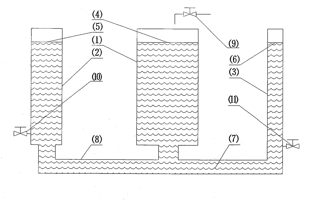
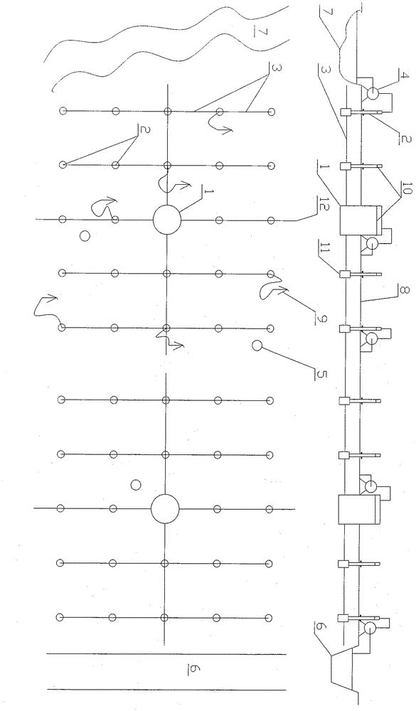
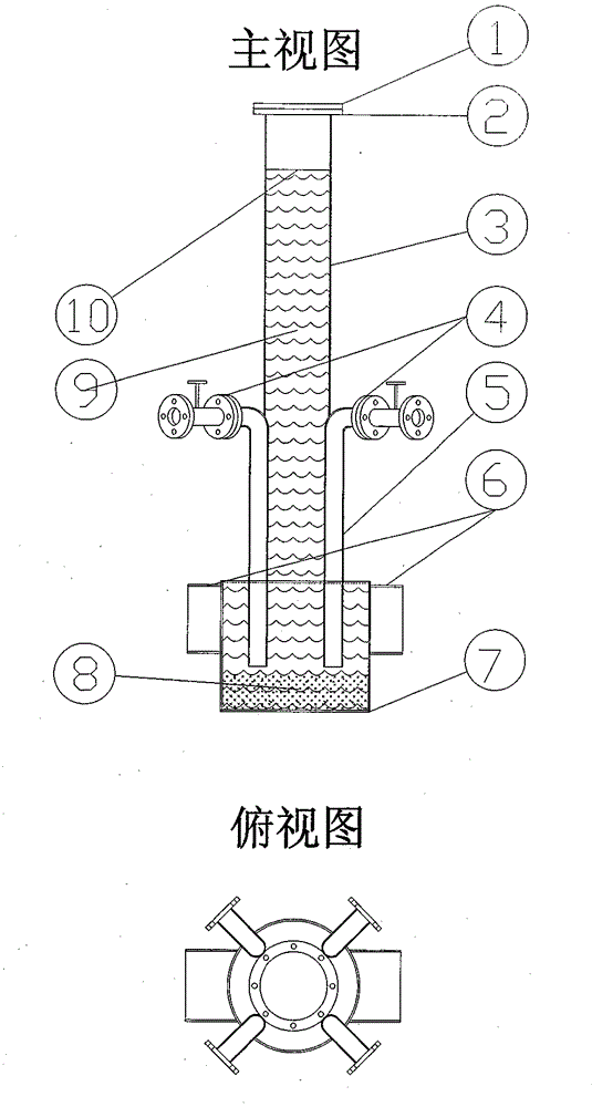
  • Connector high-efficiency water-saving irrigation water source system
  • Connector high-efficiency water-saving irrigation water source system
  • Connector high-efficiency water-saving irrigation water source system

Examples


Embodiment Construction

[0064] The present invention implements with engineering method, and concrete way is:

[0065] ■Determine the height of the reservoir and the multifunctional water intake device and the capacity of the reservoir according to the requirements of the system water level difference and buffer storage capacity;

[0066] ■Determine the interval and position of the multifunctional water intake device according to the water intake distance requirements;

[0067] ■Lay underground pipe network to connect the reservoir with the multifunctional water intake device.

[0068] Through the above steps, a large-scale grid-like connector high-efficiency water-saving irrigation water source system composed of a pipe network, a reservoir and a multi-functional water intake device can be formed.

[0069] Once the present invention is implemented as a scheme, it can greatly increase the irrigation area and reduce the irrigation cost on the basis of existing water conservancy projects, and has very...


PUM


Abstract

The invention provides an efficient water-saving communicating vessel irrigation water source system, relates to the field of agriculture and forestry irrigation, and aims to provide a water source solution for efficient water-saving irrigation. According to the solution, on the basis of the communicating vessel principle, finite water source points are transferred and copied according to required irrigation positions and the number, and the large grid-shaped communicating vessel irrigation water source system composed of a reservoir, a pipe network and a multifunctional water taking device is built in an engineering method. The efficient water-saving communicating vessel irrigation water source system is characterized in that non-power water conveying, automatic non-power water transferring and automatic pollution discharge can be achieved; the system is composed of independent system units which can constitute a large-scale irrigation water source network. By means of the solution, water sources can be completely and conveniently provided for efficient water-saving irrigation with low cost.

Description

technical field [0001] The invention relates to agriculture and forestry irrigation, in particular to providing convenient and cheap water sources for high-efficiency water-saving irrigation. Background technique [0002] High-efficiency water-saving irrigation involves three main aspects: water source construction, water delivery and improvement of water use methods. Among them, providing a water source that is easy to use and low in cost is the first problem that needs to be solved. [0003] The current high-efficiency water-saving irrigation practices mainly focus on the promotion of pipeline water delivery methods, the use of advanced irrigation technology and irrigation equipment, and the core is to try to improve water use efficiency. However, improving water use efficiency cannot improve water intake conditions and reduce water prices, and efficient water-saving irrigation will be difficult to promote without convenient and cheap water sources. [0004] In the prese...

Claims


Application Information

Patent Timeline
Patent Type & Authority Patents(China)
IPC IPC(8): A01G25/00
Inventor 汪小波
Owner 汪小波
Learn More