
Cooling water supply system of bulb tubular turbine generator set

A generator set and light bulb through-flow technology, applied in engine components, machines/engines, mechanical equipment, etc., can solve the problems of difficult layout of water supply equipment and pipelines, large diameter of cooling water pipes, and large cooling water consumption, etc. Promotion and application, good cooling effect, convenient installation and maintenance

Active Publication Date: 2012-02-15
CHINA WATER RESOURCES PEARL RIVER PLANNING SURVERYING & DESIGNING
View PDF6 Cites 3 Cited by
  • Summary
  • Abstract
  • Description
  • Claims
  • Application Information

AI Technical Summary

Problems solved by technology

Due to the large cooling capacity required by large-capacity generators, the cooling water consumption is also relatively large, resulting in relatively large diameter cooling water pipes, making it difficult to arrange water supply equipment and pipelines

Method used


Image

  • Cooling water supply system of bulb tubular turbine generator set
  • Cooling water supply system of bulb tubular turbine generator set

Examples


Embodiment 1

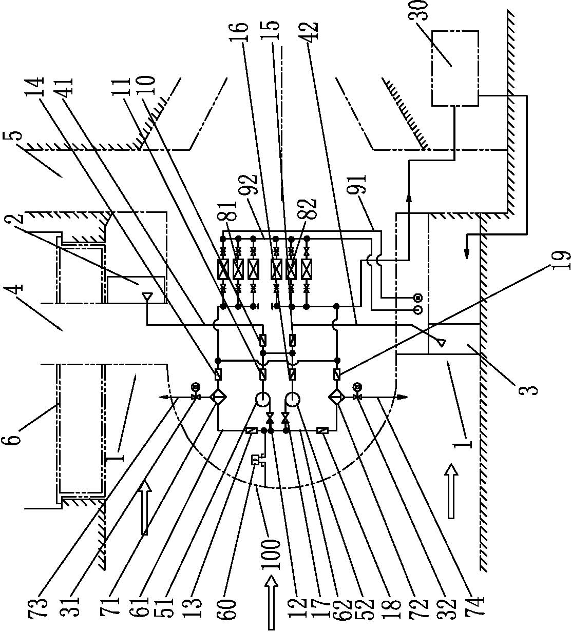
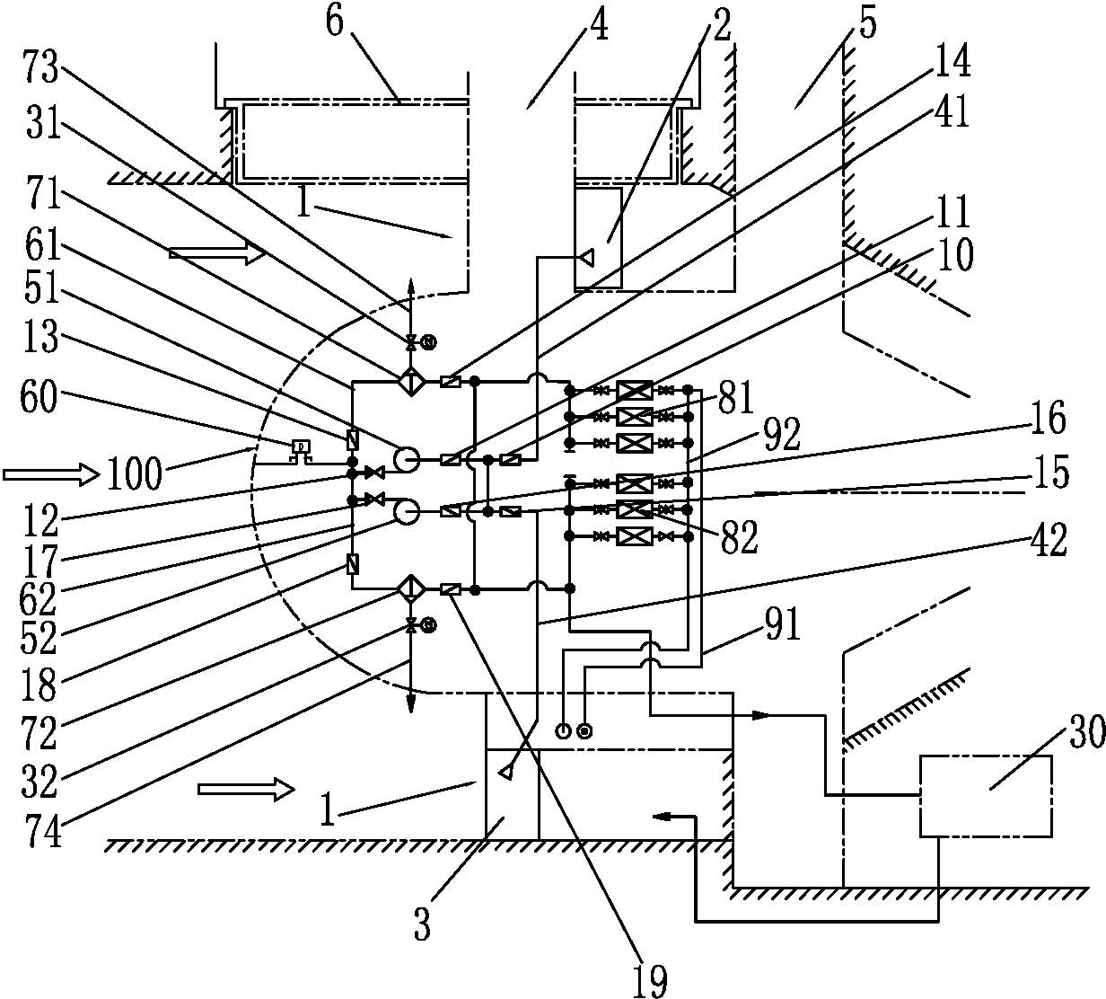
[0048] One of the specific implementations of the cooling water supply system of a bulb tubular hydroelectric generator set according to the present invention includes: the flow channel of the unit, the bulb body, the water drawer, the bearing oil cooler, and two or more sets of Cooling water supply subsystem. Among them, a flow channel cover plate is set above the flow channel of the unit; the bulb body is set in the flow channel of the unit; the water storage bin is set in the flow channel of the unit; the bearing oil cooler is set outside the flow channel of the unit; the cooling water supply subsystem is set in the bulb body Or on the runner cover, the cooling water supply subsystem includes a water suction main pipe, a water supply pump, a water outlet main pipe, an automatic water filter, a generator air cooler group, a drainage main pipe, and multiple pipes and valves; the water suction of the water suction main pipe The other end of the water suction main pipe is conne...

Embodiment 2

[0057] The second embodiment of the cooling water supply system of a bulb tubular hydroelectric generating set of the present invention is as follows: figure 1 As shown, it includes: the unit flow channel 1, the flow channel cover plate 6 is arranged above the unit flow channel 1; the bulb body 100, the bulb body 100 is arranged in the unit flow channel 1; the first water drawer 2, the The first water-drawing bin 2 is arranged in the flow channel 1 of the unit, and is located above the bulb body 100; Below: the bearing oil cooler 30, the bearing oil cooler 30 is arranged outside the flow channel 1 of the unit. Wherein, the positions of the first water-drawing bin 2 and the second water-drawing bin 3 can be arranged flexibly according to needs, and can also be considered to be arranged on the side wall of the flow channel 1 of the unit according to specific conditions.

[0058] The first cooling water supply subsystem, the first cooling water supply subsystem is arranged in th...


PUM


Abstract

The invention discloses a cooling water supply system of a bulb tubular turbine generator set. The cooling water supply system comprises a unit flow channel, a bulb, two or more groups of cooling water supply subsystems, a draw water chamber and a bearing oil cooler, wherein each cooling water supply subsystem comprises a water sucking main pipe, a water supply pump, a water outlet main pipe, an automatic water filter, a generator air cooler group, pipelines and a valve; the water supply pump is arranged in the bulb or on a flow channel cover plate, and the automatic water filter is arranged in the lamp bulb or on the flow channel cover plate; the water supply pump takes water from the draw water chamber through the water sucking main pipe and the valve, and is connected with the automatic water filter through the water outlet main pipe and the valve and then respectively connected to the generator air cooler group and the bearing oil cooler; an exhaust port of the generator air cooler group and an exhaust port of the bearing oil cooler are respectively communicated with the unit flow channel through the pipelines. The cooling water supply system provided by the invention has the characteristics of no restriction in cooling capacity, good cooling effect, good reliability and stability, easiness in manufacture, convenience in maintenance and low cost, and has application value of market promotion.

Description

technical field [0001] The invention relates to the technology of a hydroelectric generating set, in particular to a cooling water supply system of a bulb tubular type hydroelectric generating set. Background technique [0002] The cooling methods of large and medium-sized bulb tubular hydroelectric generators operating in the prior art can be summarized into the following two or two types: [0003] The first type: the secondary cycle cooling method of "air cooler-water cooler". [0004] The air cooler is located in the air circulation process of the generator cabin, which is similar to the air cooler arrangement of a common vertical unit. The "water cooler" of the bulb tubular hydroelectric generator set generally has two arrangements according to the capacity of the unit: one is in the form of a cooling jacket, that is, a section of the outer shell of the bulb body is made into a hollow interlayer, and The side in contact with the river water is made of stainless steel c...

Claims


Application Information

Patent Timeline
IPC IPC(8): F25D1/00F03B13/00
Inventor 游赞培翁映标肖毅雄黄镜湖杨类琪高琳
Owner CHINA WATER RESOURCES PEARL RIVER PLANNING SURVERYING & DESIGNING
Learn More