Stamping device of ventilation plate

A technology of stamping device and ventilation plate, which is applied in the field of mechanical equipment, can solve the problems of high mold production cost, large stamping mold area, and high pressure, and achieve the effects of reducing production cost, improving stamping precision, and reducing stamping pressure

Inactive Publication Date: 2014-03-26
JIAXING YONGFA ELECTRONICS
View PDF8 Cites 4 Cited by
  • Summary
  • Abstract
  • Description
  • Claims
  • Application Information

AI Technical Summary

Problems solved by technology

[0002] In the existing enterprise, the stamping of the ventilation plate is formed by one-time stamping. This stamping method requires multiple rows and columns of dies on the stamping mold, which makes the area of ​​the stamping mold relatively large and the production cost of the mold is high. If one of the dies is damaged during use, the entire die will be scrapped, resulting in great waste
In addition, during one-time punching, a larger pressure needs to be applied, and a larger type of punching machine needs to be used, which consumes more energy.

Method used


Image

  • Stamping device of ventilation plate
  • Stamping device of ventilation plate
  • Stamping device of ventilation plate

Examples


Embodiment 1

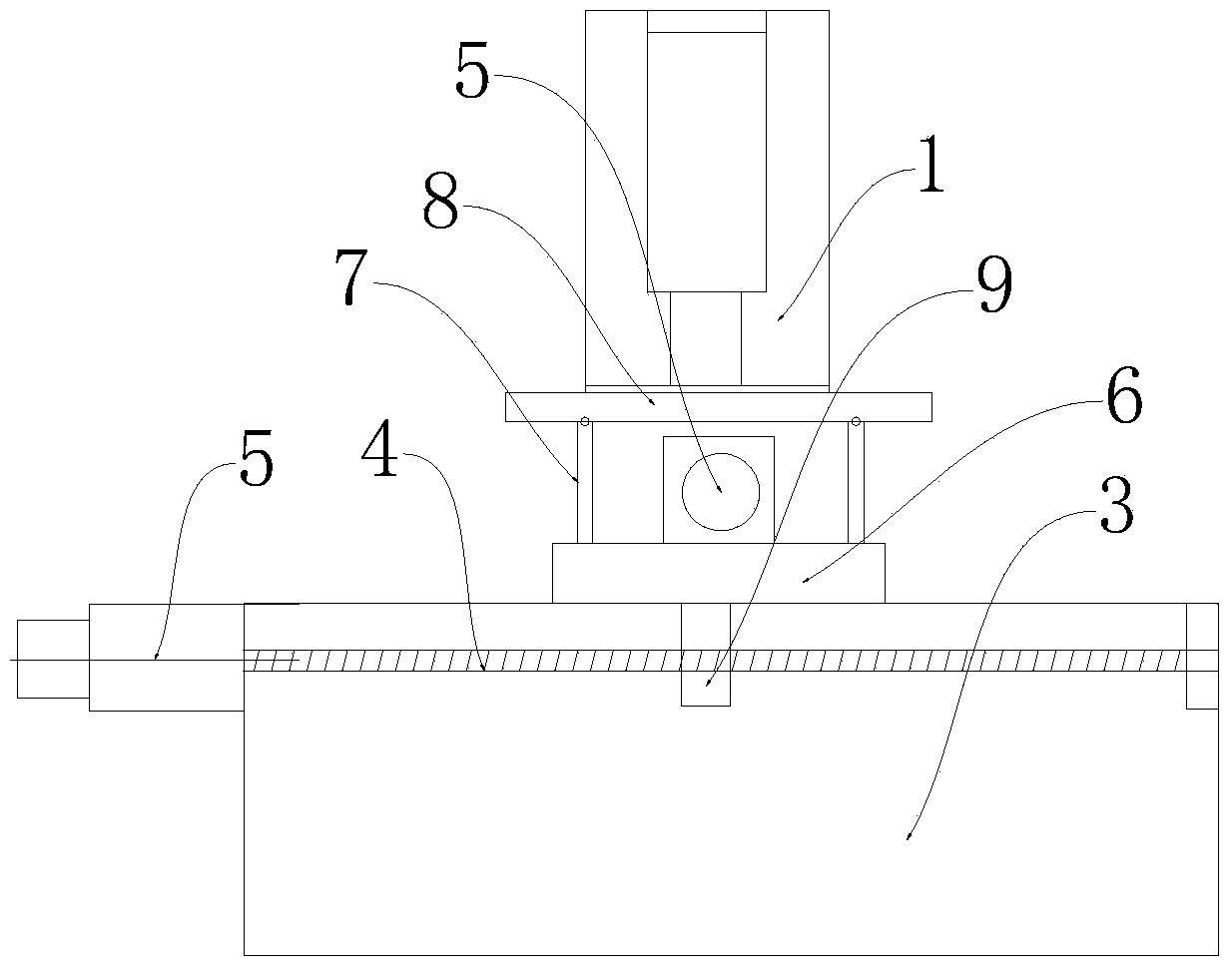
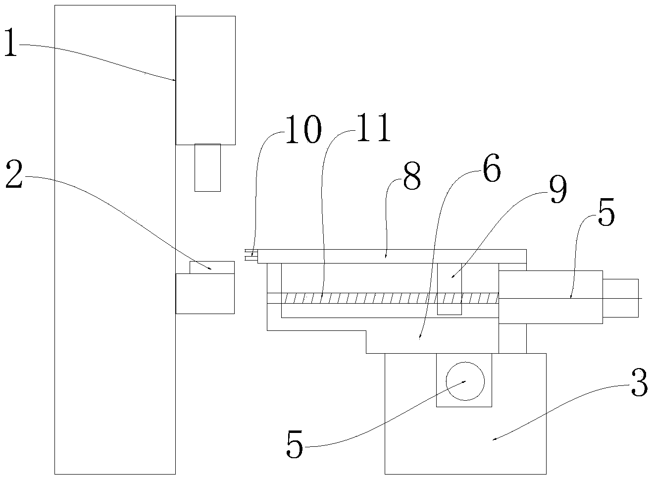
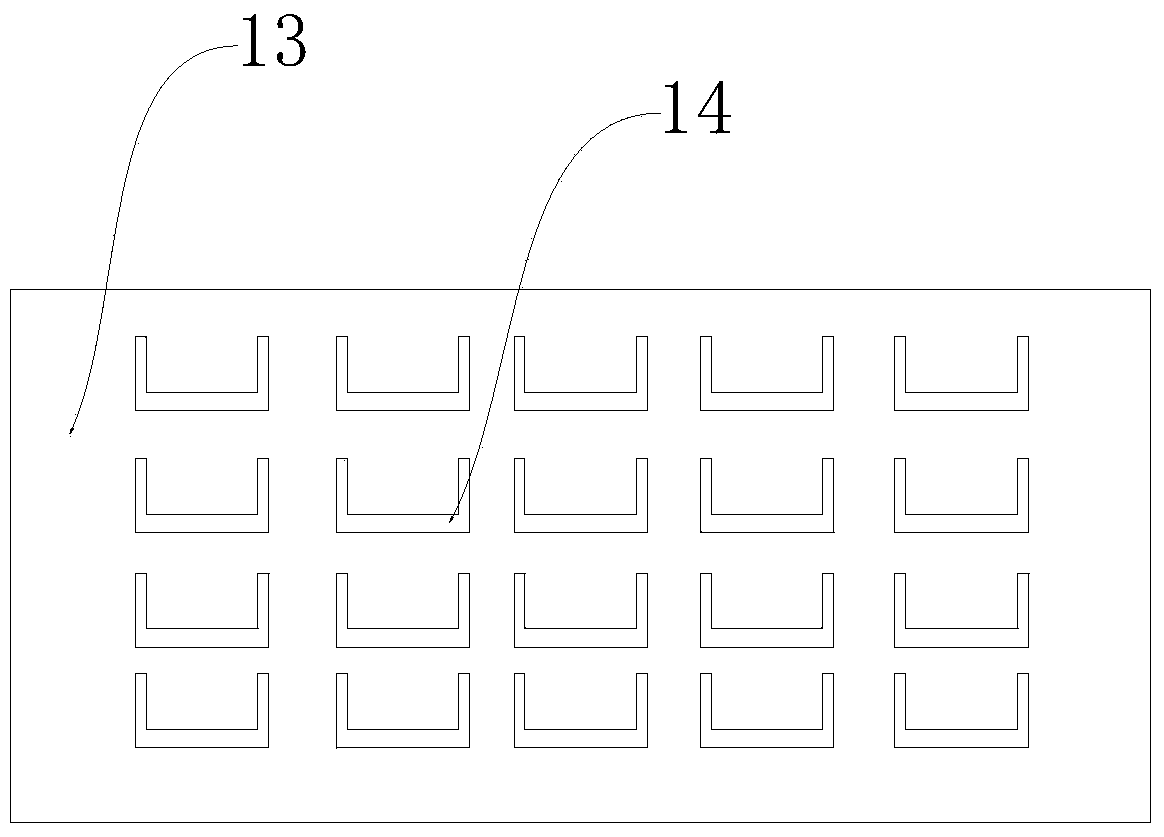
[0015] like figure 1 , figure 2 , image 3 , Figure 4 As shown, the stamping device of the ventilation plate described in this embodiment includes a punch press 1 and a moving fixture, and the stamping die 2 includes an upper mold and a lower mold, and the number and position of the depressions 12 on the lower mold are consistent with the positions of a row of openings 14 on the ventilation plate. The quantity corresponds to the position; a moving fixture is provided directly opposite the punch press 1 . The structure of the mobile fixture includes a base 3, a transverse screw 4 is arranged inside the base 3, a motor 5 is provided at one end of the transverse screw 4, a base 6 is arranged on the base 3, the base 6 can slide laterally on the base 3, and the base 6 The bottom is fixed with a nut 9, the nut 9 is sleeved on the horizontal screw 4, a longitudinal slide rail 7 is provided on the base 6, a connecting arm 8 is provided on the longitudinal slide rail 7, and a long...


PUM


Abstract

The invention relates to the field of mechanical equipment and particularly discloses a stamping device of a ventilation plate, wherein the stamping device of the ventilation plate is low in production cost and little in energy consumption. The stamping device of the ventilation plate comprises a punch press and a moving clamp, the moving clamp is arranged on the face right opposite to the punch press, the moving clamp structurally comprises a base, a pedestal is arranged on the base, a longitudinal slide rail is arranged on the pedestal, a connecting arm is arranged on the longitudinal slide rail, a nut is arranged at the bottom of the connecting arm, and the nut is arranged on a longitudinal screw rod in a sleeved mode. A pneumatic gripper is arranged on the portion, close to one end of the punch press, of the connecting arm. According to the stamping device of the ventilation plate, a row of concave dies are arranged on a stamping die, the ventilation plate is stamped many times, and thus the size of the die can be effectively reduced, the stamping pressure and energy consumption can be reduced. Through transverse motion of the pedestal and longitudinal motion of the connecting arm, the pneumatic gripper can move in the horizontal plane so that the ventilation plate can be moved and positioned. Moreover, motion of the pneumatic gripper is achieved through the screw rod and the nut, so that the pneumatic gripper performs positioning more accurately, and thus the stamping accuracy of the ventilation plate is improved.

Description

technical field [0001] The invention relates to the field of mechanical equipment, in particular to a stamping device for a ventilation panel. Background technique [0002] In the existing enterprise, the stamping of the ventilation plate is formed by one-time stamping. This stamping method requires multiple rows and columns of dies on the stamping mold, which makes the area of ​​the stamping mold relatively large and the production cost of the mold is high. If one of the dies is damaged during use, the entire die will be scrapped, causing great waste. In addition, during one-time stamping, a greater pressure needs to be applied, and a larger type of punching machine needs to be used, which consumes more energy. Contents of the invention [0003] The object of the present invention is to provide a punching device for ventilation panels with low production cost and low energy consumption in order to solve the above technical deficiencies. [0004] In order to achieve the ...

Claims


Application Information

Patent Timeline
Patent Type & Authority Applications(China)
IPC IPC(8): B21D28/02B21D43/11
Inventor 夏如忠
Owner JIAXING YONGFA ELECTRONICS
Why Eureka
Try Eureka