
Novel clamp

A fixture, a new type of technology, applied in the direction of clamping, manufacturing tools, support, etc., can solve the problems of clamping parts, complex structure of clamping methods, etc.

Inactive Publication Date: 2014-03-26
王凡业
View PDF0 Cites 2 Cited by
  • Summary
  • Abstract
  • Description
  • Claims
  • Application Information

AI Technical Summary

Problems solved by technology

[0002] In mechanical processing, some hole parts are often encountered. For these hole parts, cylindrical mandrels are usually used for centering clamping when clamping. It is necessary to limit its rotation around the axis. For this situation, there are various clamping methods in the prior art, and some even use chucks for clamping. Generally speaking, such parts are relatively precise. If you directly clamp If it is held on the peripheral surface of the part, it will often pinch the part, and the structure of this kind of clamping method is relatively complicated.

Method used


Image

  • Novel clamp

Examples


Embodiment Construction

[0011] The present invention will be described in further detail below in conjunction with the accompanying drawings.

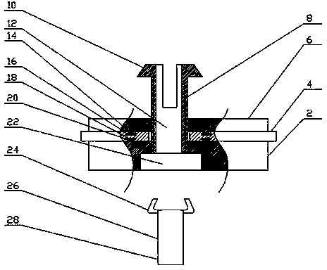
[0012] The present invention includes a base and a lifting and lowering clamping assembly arranged on the base. The expansion rod 26 in the first through hole 12 of the clamping sleeve 8, the clamping sleeve 8 is fork-shaped at least partly but including its upper end, and the upper end is provided with protrusions protruding to both sides 10. The lower surface of the raised portion 10 is a plane perpendicular to the clamping sleeve 8, and the expansion rod 26 includes a rod-shaped expansion rod body 28 that is loosely fitted with the first through hole 12 and extends to both sides. The elastic claw 24 that protrudes above the side.

[0013] Pass the hole of the workpiece through the clamping sleeve 8, and prop up the clamping sleeve 8 through the expansion rod 26. At this time, the protrusion 10 of the expansion rod 26 and the upper surface of the base pres...


PUM


Abstract

The invention discloses a novel clamp which comprises a base and a lifting clamping assembly arranged on the base. The novel clamp is characterized in that the clamping assembly comprises a lifting hollow clamping sleeve with a first through hole and a swelling rod capable of being inserted into the first through hole of the clamping sleeve, at least part, including the upper end portion of the clamping sleeve, of the clamping sleeve is in a fork shape, the upper end portion of the clamping sleeve is provided with a protruding part protruding towards the two sides, the lower surface of the protruding part is a plane perpendicular to the clamping sleeve, and the swelling rod comprises a rod-shaped swelling rod body in clearance fit with the first through hole and an elastic protruding claw protruding towards the positions above the two sides. By means of the novel clamp, a hole of a workpiece penetrates through the clamping sleeve, the clamping sleeve is supported by the swelling rod, the protruding part of the swelling rod and the upper surface of the base axially press the workpiece at the time, static friction force is accordingly generated, the swelling rod is prevented from rotating in the axial direction, the novel clamp in the mode is simple in structure, and as the clamping force is acted on the end face, the workpiece cannot be damaged by clamping.

Description

technical field [0001] The invention relates to a fixture, in particular to a fixture for clamping hole parts. Background technique [0002] In mechanical processing, some hole parts are often encountered. For these hole parts, cylindrical mandrels are usually used for centering clamping when clamping. It is necessary to limit its rotation around the axis. For this situation, there are various clamping methods in the prior art, and some even use chucks for clamping. Generally speaking, such parts are relatively precise. If you directly clamp If it is held on the peripheral surface of the part, it will often pinch the part, and the structure of this kind of clamping method is relatively complicated. Contents of the invention [0003] The technical problem to be solved by the present invention is to provide a new fixture with simple structure and not easy to pinch the workpiece. [0004] In order to solve the above problems, the present invention provides a new type of cla...

Claims


Application Information

Patent Timeline
IPC IPC(8): B23Q3/00
CPCB23Q3/00
Inventor 王凡业
Owner 王凡业
Learn More