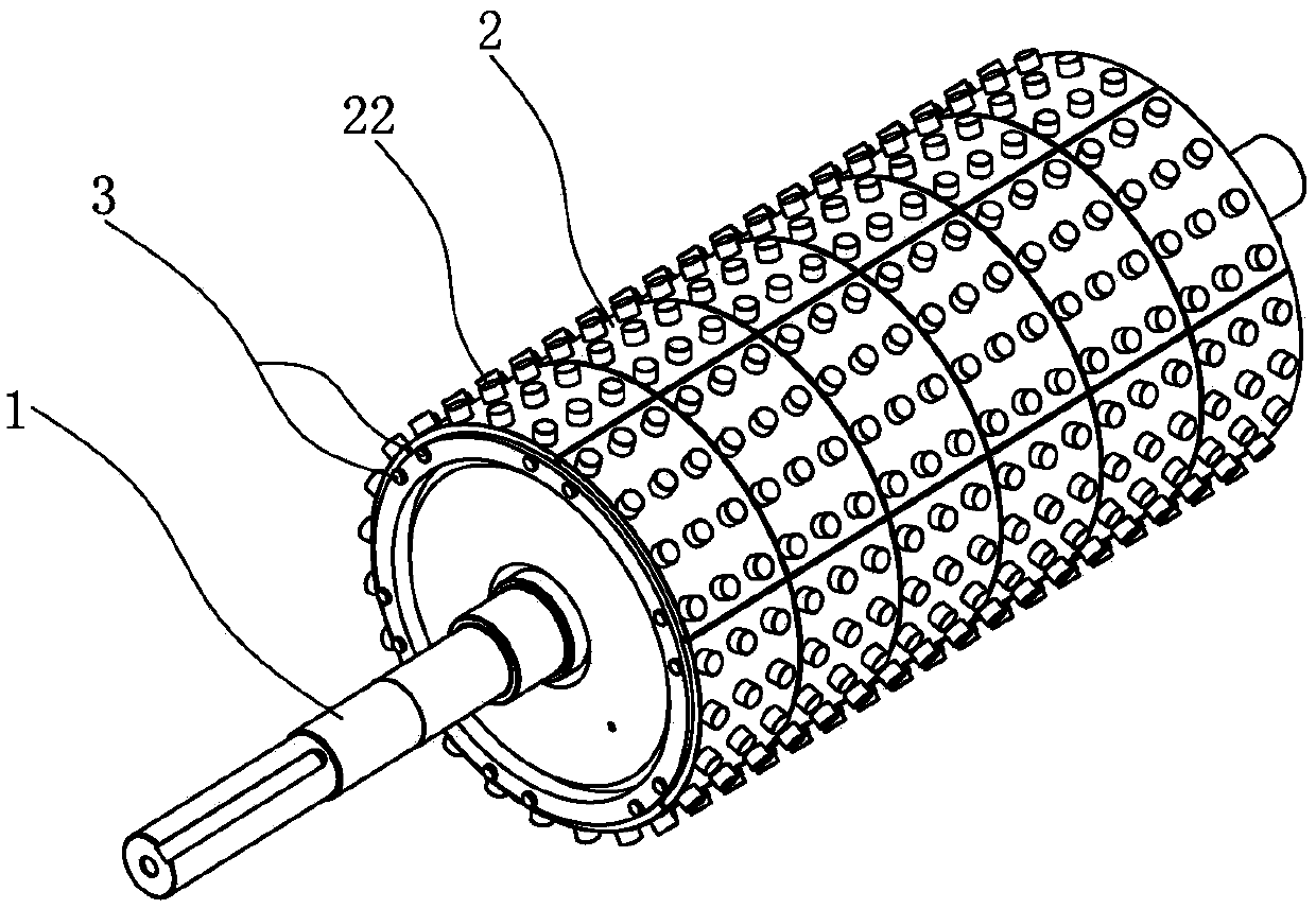
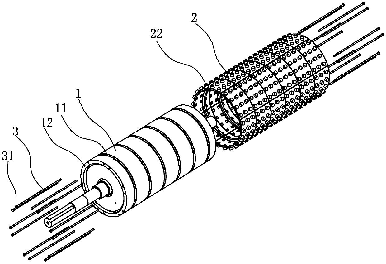
A crushing roller and an arrangement and combination method of crushing teeth of the crushing roller
A technology of crushing rollers and crushing teeth, which is applied in the direction of grain processing, etc., can solve the problems of reducing ash, waste of resources, etc., and achieve the effect of convenient replacement of tooth plates, reduction of use costs, and improvement of work efficiency
- Summary
- Abstract
- Description
- Claims
- Application Information
AI Technical Summary
Problems solved by technology
Method used
Image
Examples
Embodiment 1
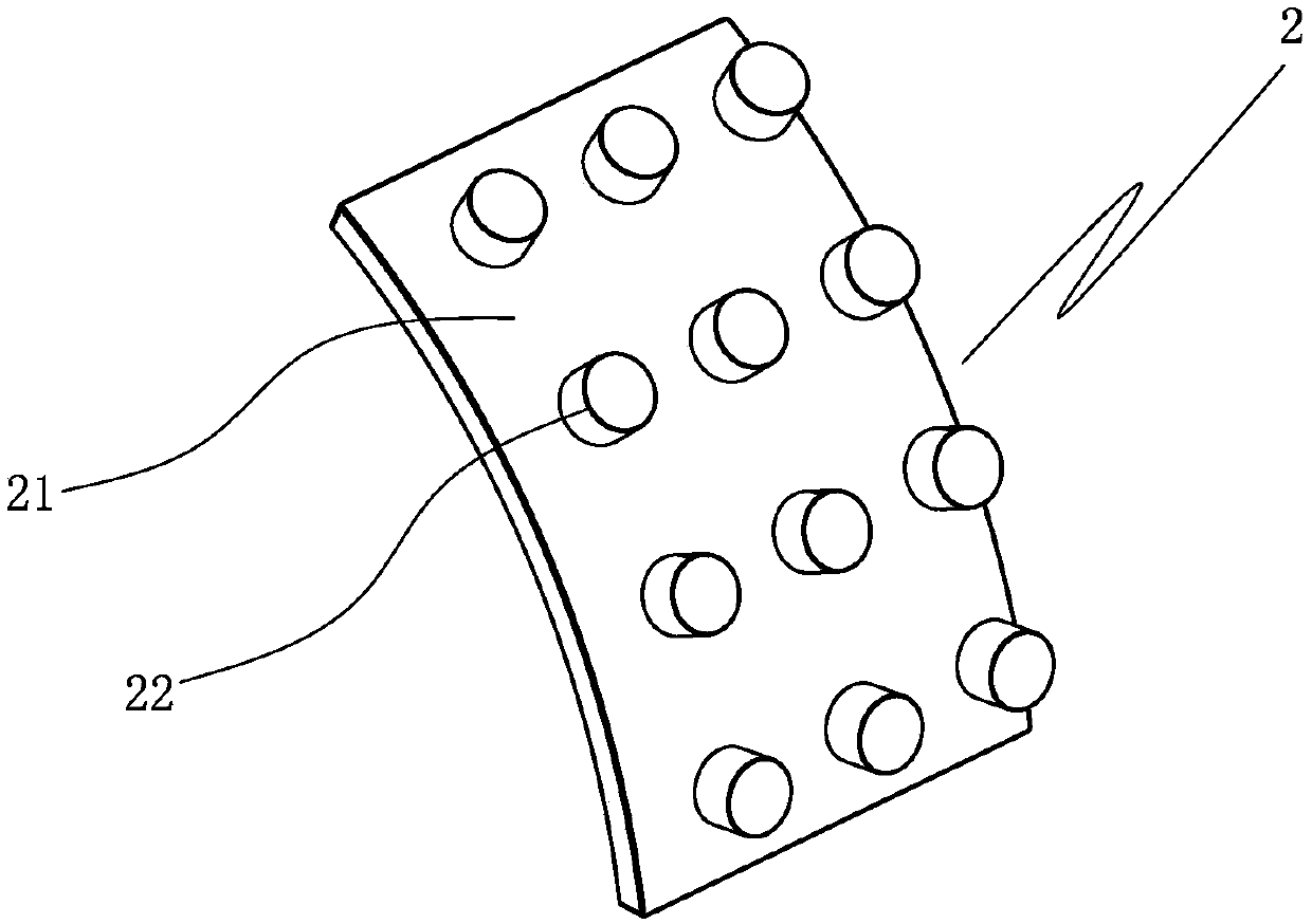
[0061] In the first embodiment, the locking mechanism 4 includes two card slots 41, two card blocks 42 and a spring 43, and the two card slots 41 are symmetrically arranged in the installation hole 211; , the connection part 222 is provided with a relief hole 223, the relief hole 223 is arranged perpendicular to the connection part 222, the two blocks 42 are arranged in the relief hole 223, and can move in a direction close to or away from the card groove 41; the spring 43 is arranged on Between the two blocks 42, located in the relief hole 223, the two ends are respectively connected with the two blocks 42 to drive the two blocks 42 to move close to or away from the slot 41. When the crushing teeth 22 are installed, press the two blocks 42 to make the two The block 42 is completely placed in the mounting hole 211, and the connecting portion 222 is pushed into the mounting hole 211. When the block 42 reaches the position of the slot 41, the two blocks 42 are not blocked by the ...
Embodiment 2
[0062] In the second embodiment, the mounting hole 211 is a circular hole, the connecting portion 222 is a cylinder, the locking mechanism 4 includes a circlip 44 for the shaft, and the connecting portion 222 includes an extension section 224 that can extend out of the mounting hole 211, and the shaft is used for The circlip 44 is used in conjunction with the protruding section 224 of the connecting part 222 to fix the crushing tooth 22 on the bottom plate 21. The diameter of the inner ring of the circlip 44 for the shaft is smaller than the diameter of the connecting part 222 in a natural state. Specifically, The side of the bottom plate 21 in contact with the roller body 1 is provided with a groove 212 communicating with the mounting hole 211, the extension section 224 of the connecting part 222 protrudes from the mounting hole 211 and extends into the groove 212, and the shaft is provided with a circlip 44 in the groove 212 is used in conjunction with the extension section 2...
Embodiment 3
[0063] In the third embodiment, the mounting hole 211 is a circular hole, the connecting portion 222 is a cylinder, and the locking mechanism 4 includes an expansion sleeve 45, and the expansion sleeve 45 is arranged between the mounting hole 211 and the connecting portion 222, and is connected to the mounting hole 211 and the connecting portion 222. The parts 222 cooperate with each other to fix the crushing teeth 22 on the bottom plate 21. When installing the crushing teeth 22, push the expansion sleeve 45 into the installation hole 211 first, and then push the connecting part 222 into the expansion sleeve 45 to realize the crushing teeth 22. Install.
PUM
 Abstract
Description
Claims
Application Information
 - R&D
- Intellectual Property
- Life Sciences
- Materials
- Tech Scout
- Unparalleled Data Quality
- Higher Quality Content
- 60% Fewer Hallucinations
Browse by: Latest US Patents, China's latest patents, Technical Efficacy Thesaurus, Application Domain, Technology Topic, Popular Technical Reports.
© 2025 PatSnap. All rights reserved.Legal|Privacy policy|Modern Slavery Act Transparency Statement|Sitemap|About US| Contact US: help@patsnap.com


