
Medium conveying device, control method of medium conveying device, and recording device

A medium conveying and control technology, applied in printing devices, transportation and packaging, thin material processing, etc., can solve problems such as recording medium wrinkles

Inactive Publication Date: 2017-05-10
SEIKO EPSON CORP
View PDF5 Cites 0 Cited by
  • Summary
  • Abstract
  • Description
  • Claims
  • Application Information

AI Technical Summary

Problems solved by technology

Therefore, when the conveyance is stopped, if the meander correction unit continues to be driven, only the recording medium on the upstream side of the intermediate roller will move in the width direction, so wrinkles will be generated in the recording medium (fabric) near the intermediate roller.

Method used


Image

  • Medium conveying device, control method of medium conveying device, and recording device
  • Medium conveying device, control method of medium conveying device, and recording device
  • Medium conveying device, control method of medium conveying device, and recording device

Examples


Embodiment Construction

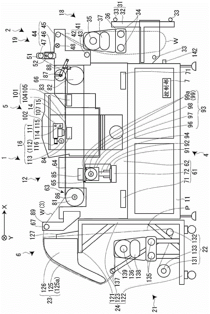
[0024] Hereinafter, an inkjet recording device 1 according to an embodiment of the present invention will be described with reference to the drawings. This inkjet recording device 1 inkjet-prints characters, patterns, etc. using a dedicated dye ink on a fabric that feeds and receives materials in a so-called reel-to-reel format (printing). In addition, in the following description, the forward and reverse conveyance direction of the recording medium W as a fabric is defined as the X-axis direction, the direction perpendicular to the X-axis direction is defined as the Y-axis direction, and the direction perpendicular to the X-axis direction and The direction of the Y-axis direction is defined as the Z-axis direction.

[0025] figure 1 is a cross-sectional configuration diagram of the inkjet recording device 1 . As shown in the figure, the inkjet recording apparatus 1 includes an ejection unit 2 that ejects and conveys a recording medium W wound in a roll shape, and an apparat...


PUM


Abstract

The present invention provides a medium conveying device, a method of controlling the medium conveying device, and a recording device capable of reliably correcting meandering without causing wrinkles to the recording medium in a medium conveying device intermittently conveying the recording medium. A zigzag detection sensor (48) for detecting positional deviation of the recording medium (W) in the width direction, and a control unit ( 7) The control unit 7 stops the drive of the width moving unit (36) when the intermittent conveyance is stopped.

Description

technical field [0001] The present invention relates to a medium conveying device that feeds and conveys a recording medium such as cloth wound into a roll, a control method of the medium conveying device, and a recording device. Background technique [0002] Conventionally, an inkjet printer is known that includes a conveyance unit that conveys a fabric along a conveyance path, an unwinding portion that unwinds a fabric wound into a roll, and is provided on the conveyance path between the unwinder and the conveyance unit. Intermediate rollers that change the curvature of the conveying path, meandering (snaking) correction units that move the fabric in the width direction through the unwinding unit, meandering detection sensors that detect the meandering of the fabric fed into the conveying unit, and The detection result of the inkjet printer is a control unit that controls the drive of the meander correcting unit, and the inkjet printer corrects the meandering of the fabric...

Claims


Application Information

Patent Timeline
Patent Type & Authority Patents(China)
IPC IPC(8): B41J15/04B41J15/16
CPCB41J15/046B41J15/048B41J15/16B65H23/0216B65H2557/62B65H2801/15B65H2301/41346B65H2301/4493B65H2403/52B65H2511/112B65H2515/31B65H2553/414B65H2701/174B65H2801/36B65H23/0326B65H2515/84B65H2220/01B65H2220/02B65H23/038B41J15/04B65H20/08B41J13/0009
Inventor 上妻格
Owner SEIKO EPSON CORP
Learn More