Environment-friendly disaster relief tent and method for unfolding and folding tent frame

A tent and environmental protection technology, applied in the field of tents, can solve problems such as unfavorable recycling, affecting assembly, complex processing technology, etc., and achieve the effects of convenient recycling and secondary utilization, convenient installation and removal, and simple production process.

Active Publication Date: 2014-03-26
HEBEI JIAYIN TENT MFG
View PDF9 Cites 11 Cited by
  • Summary
  • Abstract
  • Description
  • Claims
  • Application Information

AI Technical Summary

Problems solved by technology

[0002] At present, the tents on the market are combined with tent frames and tarpaulins, and there are also tent frames and tarpaulins that are set separately. ) Room-type tents are set separately from the tent frame and the tarpaulin, and most of the existing large-scale tent frames for disaster relief are made of multiple individual poles connected by plugs or connectors, that is, the poles are connected to the joints. The parts are all set separately. It is necessary to install and combine the poles and connecting parts one by one when the tent is spliced ​​on site. The connectors are all disassembled and not connected to each other, so they may be lost during transportation, and they are also easy to be lost during asse

Method used


Image

  • Environment-friendly disaster relief tent and method for unfolding and folding tent frame
  • Environment-friendly disaster relief tent and method for unfolding and folding tent frame
  • Environment-friendly disaster relief tent and method for unfolding and folding tent frame

Examples


Embodiment 1

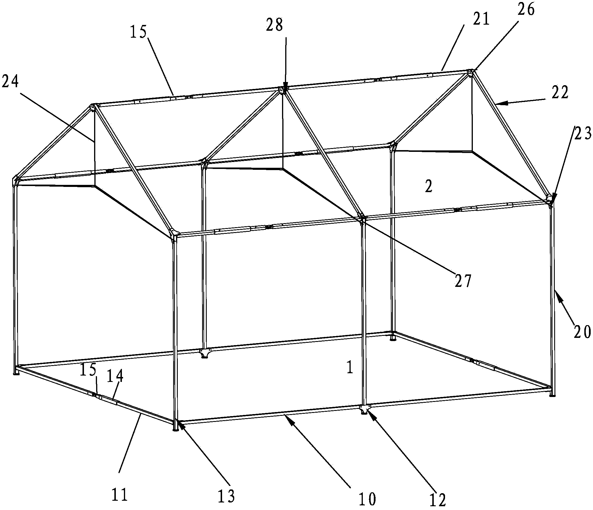
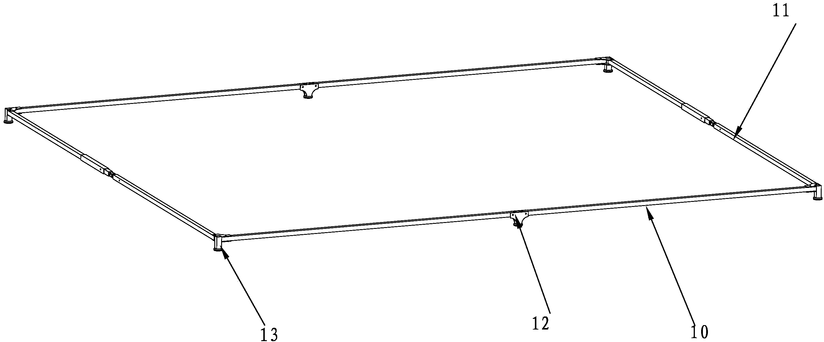
[0050] Such as figure 1 and figure 2 As shown, the base 1 is rectangular after stretching, including four ground poles 10 on both sides in the long side direction, four gable ground poles 11 in the short side direction, and a base for connecting two ground poles 10 on both sides. The middle socket 12, the base angle socket 13 for connecting the ground poles 10 on both sides and the gable ground poles 11, the two gable ground poles 11 are connected by a pivotal connection device 15, and can be rotated and connected by 180-degree folding, and A sleeve 14 is provided outside the pivotal connection device. When the base is unfolded, the sleeve 14 is placed outside the pivotal connection device 15 to increase the rigidity of the base. When it needs to be folded, the sleeve 14 can be moved to make the pivotal connection device 15 for 180-degree folding. The cross-sectional shape of the sleeve 14 is consistent with the cross-sectional shape of the gable ground pole 11 .

[0051] ...

Embodiment 2

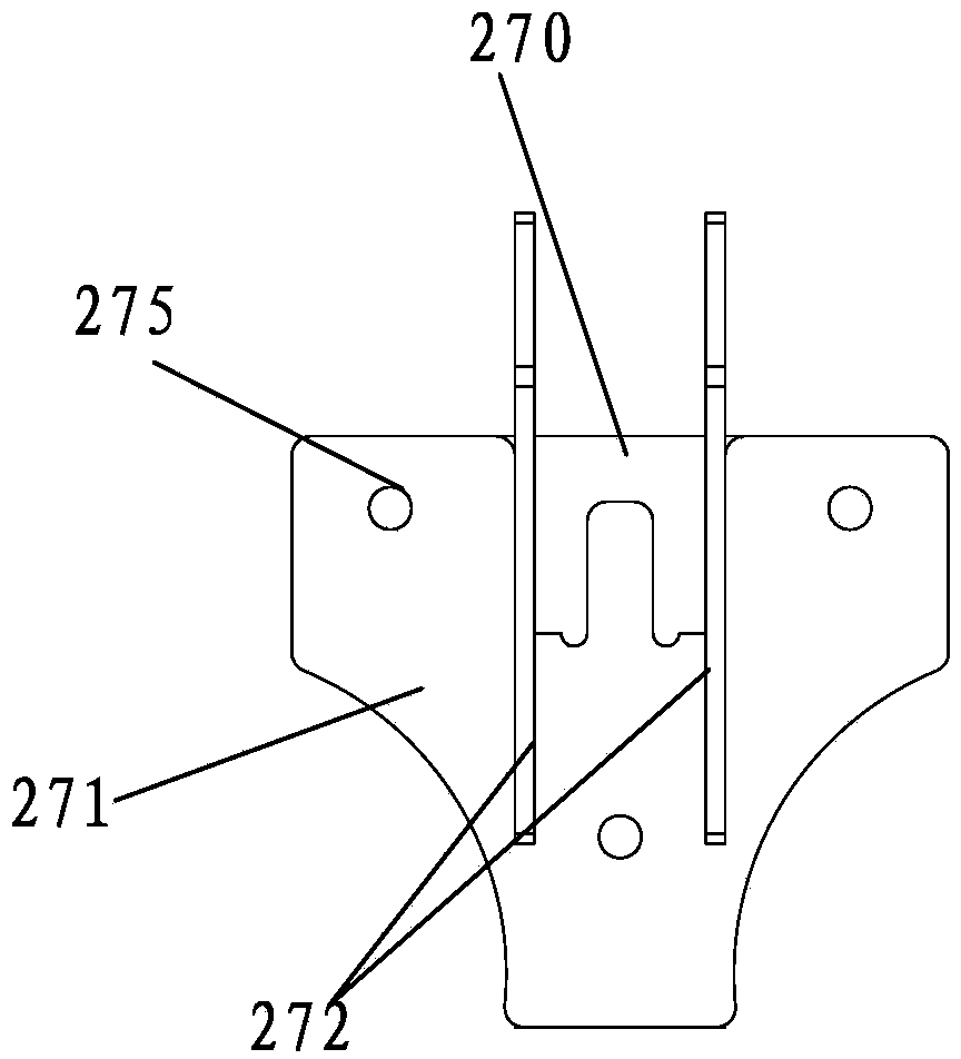
[0067] This embodiment is on the basis of the above-mentioned embodiment, and the eaves corner socket 23 that is used to connect the vertical rod 20, the universal rod 22 and the oblique rod 21 to the support frame is improved, as Figure 13 As shown, the eaves corner socket 23 is welded together by one eaves corner plate 230, one eaves corner hanging plate 231 and two eaves corner risers 232, wherein the eaves corner riser 232 is exactly the same as the eaves middle hanging plate 272, forming an obtuse angle Triangular, and on one side of the hypotenuse, there is a groove 233 for inserting the eaves corner board 231. Two eaves corner risers 232 are welded on one side of the eaves corner board 230 in parallel, and then the eaves corner board 231 is inserted into the eaves The grooves 233 of the angle risers 232 are welded and fixed, thus forming three through slots 234 that can be pivotally connected with the vertical bar 20, the universal bar 22 and the inclined bar 21 respect...

Embodiment 3

[0069] This embodiment is on the basis of the above-described embodiment, and the socket 28 in the ridge used to connect the universal rod 22 and the oblique rod 21 to the support frame is improved, as Figure 15 As shown, the socket 28 in the ridge is formed by welding two diamond-shaped plates 280 and a bent plate 281, wherein the bent plate 281 is directly punched and then bent to form a metal plate, as Figure 17 and Figure 18 As shown, there are parallel wing plates 282 on both sides and a connecting plate 283 for connecting the two wing plates 282 as a whole. The square groove 284 that wing plate 282 inserts, as Figure 16 As shown, four through slots 285 for the pivot connection of the two oblique rods 21 and the two universal rods 22 are formed.


PUM

PropertyMeasurementUnit
Wall thicknessaaaaaaaaaa

Abstract

The invention discloses an environment-friendly disaster relief tent. The environment-friendly disaster relief tent is composed of a tent body, a cotton inner container, a frame, a shakedown and accessories. The frame comprises a base and a supporting frame, wherein the base comprises four base two-side ground rods, four gable ground rods, four base corner sockets and two base middle sockets, every two adjacent gable ground rods are connected through a pivotal connecting device, the supporting frame comprises six vertical rods, six inclined rods, four eaves corner sockets, two eaves middle sockets, two ridge end sockets, a ridge middle socket and twelve universal rods, every two adjacent universal rods are connected through a pivotal connecting device which can be folded in a 180-degree mode, each eaves middle socket comprises an eaves middle upper plate, an eaves middle insertion plate and two eaves middle hanging plates, each eaves middle hanging plate is of an obtuse triangle shape, a groove is formed in one side of a bevel edge of each obtuse triangle, each eaves middle insertion plate can be inserted into the corresponding groove, the two eaves middle hanging plates of each eaves middle socket are welded to one side of the eaves middle upper plate of the eaves middle socket in a parallel mode, the eaves middle insertion plates are directly inserted into the grooves of the eaves middle hanging plates respectively, and are fixed in a welding mode, and four through grooves are formed so that the vertical rods, the universal rods and the inclined rods can be connected in a pivotal mode through the through grooves.

Description

technical field [0001] The present invention relates to a tent, more specifically, to a large-scale tent that is easy to deploy and withdraw and a method for deploying and withdrawing the tent frame. Background technique [0002] At present, the tents on the market are combined with tent frames and tarpaulins, and there are also tent frames and tarpaulins that are set separately. ) Room-type tents are set separately from the tent frame and the tarpaulin, and most of the existing large-scale tent frames for disaster relief are made of multiple individual poles connected by plugs or connectors, that is, the poles are connected to the joints. The parts are all set separately. It is necessary to install and combine the poles and connecting parts one by one when the tent is spliced ​​on site. The connectors are all disassembled and not connected to each other, so they may be lost during transportation, and they are also easy to be lost during assembly, and they are easy to be co...

Claims


Application Information

Patent Timeline
IPC IPC(8): E04H15/44E04H15/48
Inventor 唐保义
Owner HEBEI JIAYIN TENT MFG
Why Eureka
Try Eureka