Device and method for suppressing suction vortex of aircraft fuel pump

A technology of suppressing device and fuel pump, which is applied to the components, pump, pump element, etc. of the pumping device for elastic fluid, which can solve the problem of the inability to continuously supply fuel that meets the requirements of the vapor-liquid ratio and pressure, and reduce the fuel pump and fuel system. Reliability, damage to the surface and structure of overcurrent components, etc., to improve aircraft economy, reduce unavailable fuel, and improve performance

Active Publication Date: 2016-04-20
JINCHENG NANJING ELECTROMECHANICAL HYDRAULIC PRESSURE ENG RES CENT AVIATION IND OF CHINA
View PDF3 Cites 0 Cited by
  • Summary
  • Abstract
  • Description
  • Claims
  • Application Information

AI Technical Summary

Problems solved by technology

[0003] An important factor affecting the amount of unusable fuel in the aircraft fuel system is the minimum height of the oil level at the inlet of the fuel pump when the fuel pump continuously sucks fuel with a vapor-liquid ratio less than a certain value. The fuel pump starts to inhale air when the oil level of the fuel tank is higher than a certain height of its suction port, and cannot continuously provide fuel that meets the vapor-liquid ratio and pressure requirements, resulting in the actual working minimum oil level being higher than the theoretical minimum oil level by a certain value, making the aircraft The amount of unusable fuel increases, and the range and economy decrease
In addition, the suction vortex entrains air into the fuel pump, which will cause cavitation of flow-passing components such as the pump impeller and vortex chamber, damage the surface and structure of flow-passing components, and reduce the reliability of the fuel pump and fuel system
[0004] Usually, an axial-flow impeller coaxial with the impeller of the fuel pump (also known as an inducer) is added at the suction port of the fuel pump to improve the suction performance of the fuel pump. The suppression effect is limited, the rotation of the fuel at the suction port of the pump and the sinking of the oil level sometimes worsen, and the amount of unusable fuel is still large

Method used


Image

  • Device and method for suppressing suction vortex of aircraft fuel pump
  • Device and method for suppressing suction vortex of aircraft fuel pump
  • Device and method for suppressing suction vortex of aircraft fuel pump

Examples


Embodiment Construction

[0016] For specific implementation, see Figure 1 to Figure 4 . The present invention will be further described in detail through specific embodiments below.

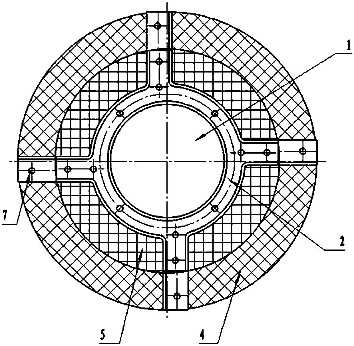
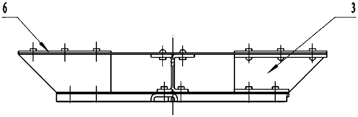
[0017] Such as figure 1 and figure 2 As shown, an aircraft fuel pump suction vortex suppression device is provided with a through hole 1 for inserting the fuel pump in the middle, a mounting bracket 2 and more than three supporting ribs 3 constitute the installation structure of the device, and on the top of the installation structure A layer of ring-shaped upper net 4 is laid, and a ring-shaped lower net 5 is laid under the installation structure. The upper net 4 is fixed by side strips 6 and rivets 7. The upper net 4 and lower net 5 form a damping net, and more than three supporting ribs 3 form a radiation shaped damping ribs.

[0018] The supporting rib 3 is a thin-plate structural member, and its web has no holes or several small holes with a diameter less than 30mm.

[0019] The upper net 4 and the lower net ...


PUM


Abstract

The invention belongs to the technical field of aircraft fuel and particularly relates to a device and method for hindering a sucked vortex of an aircraft fuel pump. The sucked vortex hindering device is composed of an installation structure, a radiating rib plate, a damping net and the like. The hindering method includes the following steps that the sucked vortex hindering device is arranged at an inlet of the fuel pump, the radiating rib plate and the net-shaped structure are used for boosting rotation at the inlet of the fuel pump and damping of downwash flow, and generation of the sucked vortex can be obviously relieved and delayed, thus the lowest oil level where the aircraft fuel pump practically works is obviously lowered. The amount of unavailable fuel of an aircraft is reduced and reliability of a fuel system is improved. The voyage of the aircraft is enlarged and economical efficiency is improved. The device and method for hindering the sucked vortex of the aircraft fuel pump are convenient to implement, wide in application and high in cost-effectiveness.

Description

technical field [0001] The invention belongs to the technical field of aviation fuel, in particular to an aircraft fuel pump suction vortex suppression device and method. Background technique [0002] The suction vortex of the aircraft fuel pump refers to the phenomenon that the oil surface around the suction port of the fuel pump rotates and sags when the fuel pump is working, and the oil level lowers and sucks in air. [0003] An important factor affecting the amount of unusable fuel in the aircraft fuel system is the minimum height of the oil level at the inlet of the fuel pump when the fuel pump continuously sucks fuel with a vapor-liquid ratio less than a certain value. The fuel pump starts to inhale air when the oil level of the fuel tank is higher than a certain height of its suction port, and cannot continuously provide fuel that meets the vapor-liquid ratio and pressure requirements, resulting in the actual working minimum oil level being higher than the theoretical...

Claims


Application Information

Patent Timeline
Patent Type & Authority Patents(China)
IPC IPC(8): F04D29/66
Inventor 郝定武林艳艳
Owner JINCHENG NANJING ELECTROMECHANICAL HYDRAULIC PRESSURE ENG RES CENT AVIATION IND OF CHINA
Why Eureka
Try Eureka