
Filling valve of vertical type injection molding machine

A technology for injection molding machines and filling valves, applied in mechanical equipment, fluid pressure actuation devices, fluid pressure actuation system components, etc. Liquid valve spool open state and other problems

Inactive Publication Date: 2014-03-26
SUZHOU LIZHU MACHINERY
View PDF6 Cites 0 Cited by
  • Summary
  • Abstract
  • Description
  • Claims
  • Application Information

AI Technical Summary

Problems solved by technology

[0003] The vertical distance between the hydraulic oil tank of the vertical injection molding machine and the filling valve is relatively large. Therefore, the hydraulic oil in the oil suction pipe has a large gravitational potential energy, which pulls the filling valve spool in the closing direction, and the piston in the hydraulic cylinder moves downwards. The vacuum suction generated by the movement is not enough to keep the spool of the filling valve open, especially when the piston just starts to move downward, the spool is often still in the closed state, which reduces the oil inlet speed of the hydraulic cylinder and affects the injection molding machine. injection molding efficiency

Method used


Image

  • Filling valve of vertical type injection molding machine
  • Filling valve of vertical type injection molding machine
  • Filling valve of vertical type injection molding machine

Examples


Embodiment Construction

[0021] The following will clearly and completely describe the technical solutions in the embodiments of the present invention with reference to the drawings in the embodiments of the present invention.

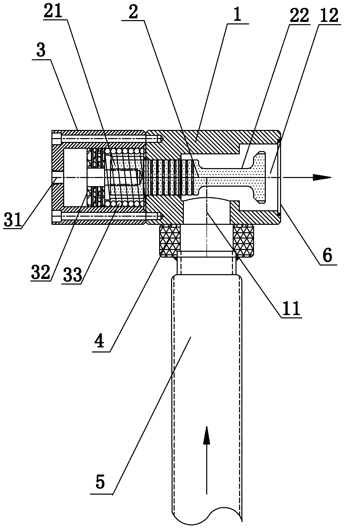
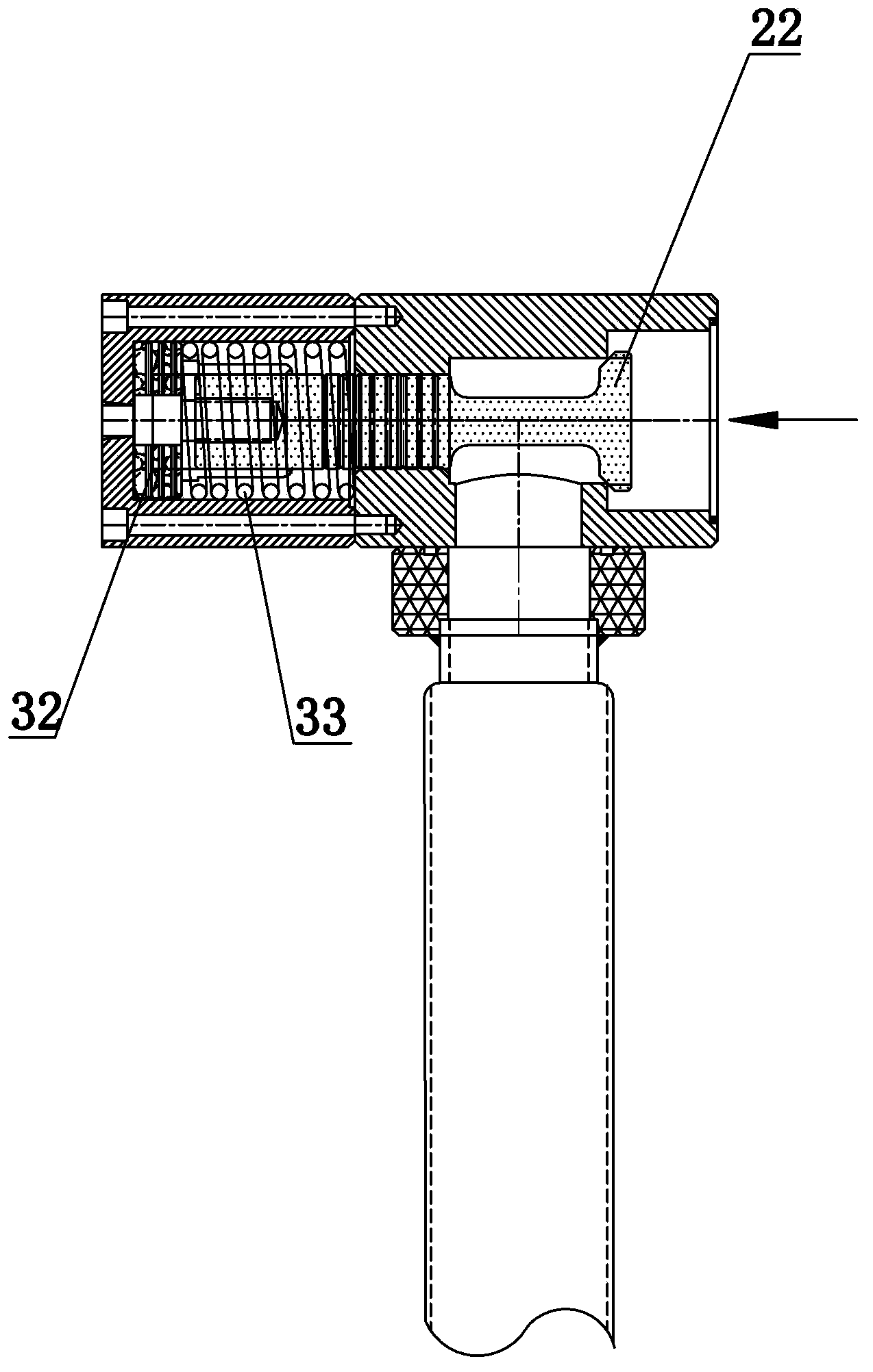
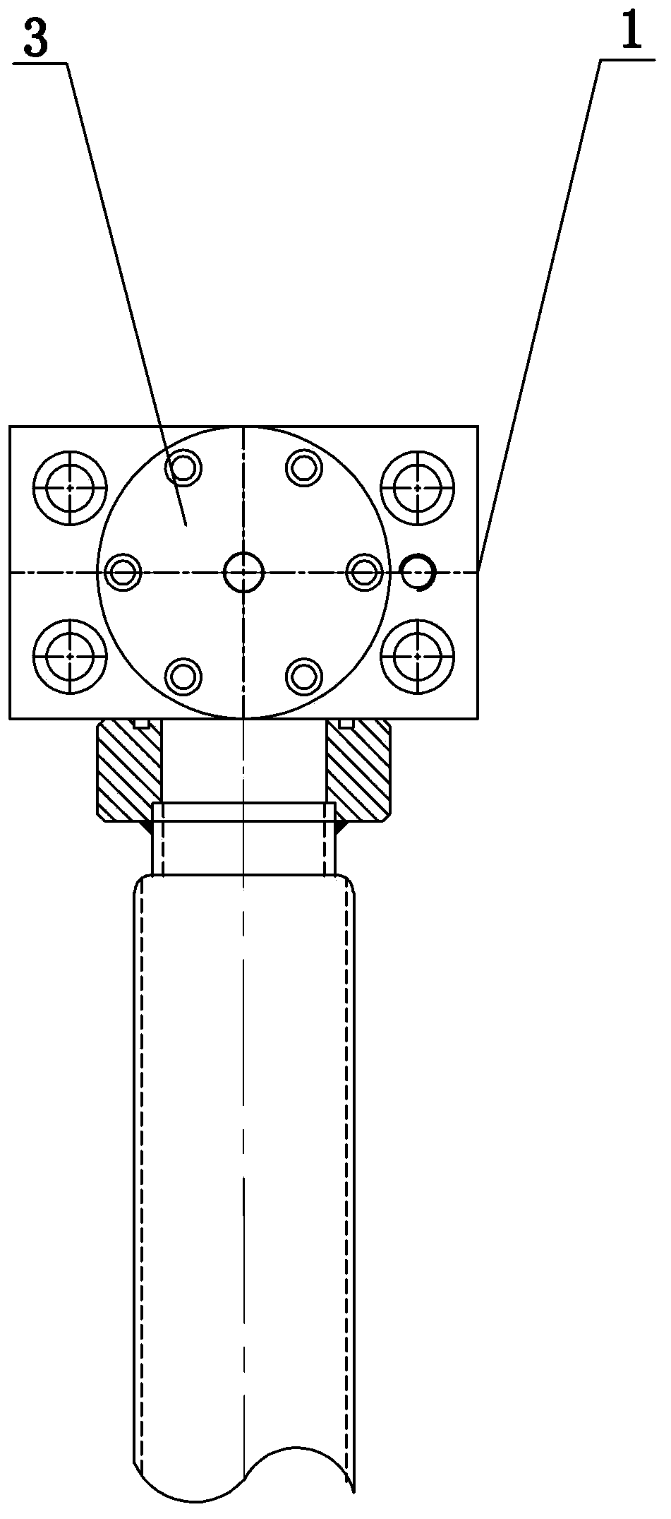
[0022] according to Figures 1 to 3 , the present invention provides a liquid filling valve for a vertical injection molding machine, comprising a valve body 1 with an oil inlet hole 11 at the bottom, an oil outlet hole 12 on the right side, and a valve core arranged in the cavity of the valve body 1 2. The left side of the valve body 1 is also fixedly connected with the valve core cylinder liner 3 provided with the pressure oil inlet hole 31 with screws, wherein the valve core 2 includes a leading end 21 and a sealing end 22, and the leading end 21 is fixed with a screw A spool piston 32 is fixedly connected, and the spool piston 32 is provided with a return spring 33 on the side close to the leading end 21, and the other end of the return spring 33 is connected with the valv...


PUM


Abstract

The invention discloses a filling valve of a vertical type injection molding machine. The filling valve of the vertical type injection molding machine comprises a valve body and a valve element, wherein the valve body is provided with an oil inlet hole and an oil outlet hole, the valve element is arranged inside a cavity of the valve body, a valve element cylinder sleeve is fixedly arranged on the lateral face of the valve body, a pressure oil inlet hole is formed in the lateral face of the valve element cylinder sleeve, the valve element comprises a front guide end and a sealing end, a valve element piston is fixedly arranged at the front guide end, a reset spring is arranged at the side, close to the front guide end, of the valve element piston, and the other end of the reset spring is connected with the valve body. The filling valve of the vertical type injection molding machine comprises the valve body, the valve element and the valve element cylinder sleeve, before a piston inside a hydraulic oil cylinder moves downwards, pressure oil is injected into the valve element cylinder sleeve in advance, the valve element is in a completely open state, and therefore the purposes of improving the oil feeding speed of the hydraulic oil cylinder and improving the injection molding efficiency of the injection molding machine are achieved.

Description

technical field [0001] The invention relates to a liquid filling valve, in particular to a liquid filling valve for a vertical injection molding machine. Background technique [0002] The liquid filling valve generally includes a valve body and a valve core, which acts as a one-way check between the hydraulic oil tank and the hydraulic cylinder. The oil outlet hole of the valve body is connected with the oil inlet hole of the hydraulic cylinder. When the piston in the hydraulic cylinder goes down When it is moving, it will pull out the vacuum to suck the valve core open, and suck the hydraulic oil in the hydraulic oil tank into the hydraulic cylinder, and when the piston pressurizes upward, the hydraulic oil in the hydraulic cylinder will press the valve core against the valve body to release the oil. Holes are sealed to prevent backflow of hydraulic oil. [0003] The vertical distance between the hydraulic oil tank of the vertical injection molding machine and the filling ...

Claims


Application Information

Patent Timeline
Patent Type & Authority Applications(China)
IPC IPC(8): F15B21/00
Inventor 骆小锋
Owner SUZHOU LIZHU MACHINERY
Learn More