U-shaped nail

A U-shaped and nail-cap technology, applied in the field of U-shaped nails, can solve the problems of waste of resources, bending of the U-shaped nails, and the inability to reuse the U-shaped nails, so as to save time in construction and realize the effect of reuse.

Inactive Publication Date: 2014-03-26
TIANJIN LINGYU METAL PROD MFG
View PDF0 Cites 4 Cited by
  • Summary
  • Abstract
  • Description
  • Claims
  • Application Information

AI Technical Summary

Problems solved by technology

[0002] The existing U-shaped nails are not easy to be pulled out after being nailed into the object. If the U-shaped nails are pulled ha...

Method used


Image

  • U-shaped nail

Examples


Embodiment Construction

[0009] The preferred embodiments of the present invention will be described in detail below.

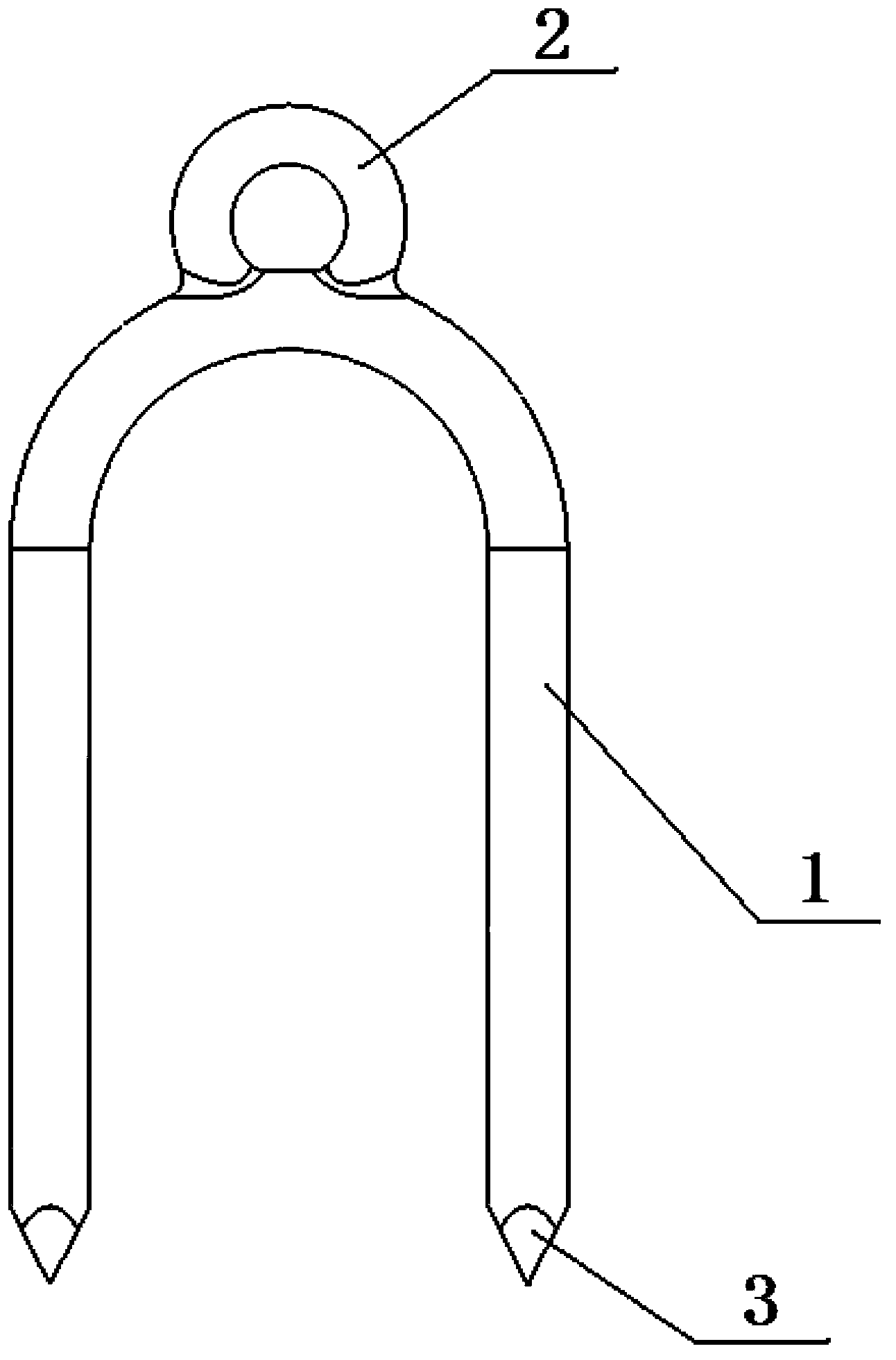
[0010] Such as figure 1 As shown, the present invention provides a U-shaped nail, comprising a nail body 1, a nail cap 2 and a nail point 3, characterized in that: the nail cap 2 is annular, and the nail cap 2 and the nail body 1 are integrated, The nail tip 3 is conical with four cut surfaces.

[0011] The manufacturing process of the present invention: because the nail cap and the nail body are integrated, only one set of pouring molds is needed for mass production.

[0012] An embodiment of the present invention has been described in detail above, but the content described is only a preferred embodiment of the present invention, and cannot be considered as limiting the implementation scope of the present invention. All equivalent changes and improvements made according to the application scope of the present invention shall still belong to the scope covered by the patent of the ...


PUM


Abstract

The invention provides a U-shaped nail which comprises a nail body, a nail head and nail points. The U-shaped nail is characterized in that the nail head is annular, the nail cap and the nail body are integrated, and each nail tip is in a cone shape with four sections. Each conical nail tip with the four sections can be conveniently and quickly nailed into a nailed object, the annular nail cap can be used for conveniently pulling out the U-shaped nail which is nailed into the object, and secondary utilization of the U-shaped nail is achieved.

Description

technical field [0001] The invention belongs to the field of nail making, in particular to a U-shaped nail. Background technique [0002] The existing U-shaped nails are not easy to be pulled out after being nailed into an object. If the U-shaped nails are pulled hard, the U-shaped nails may even be bent and broken, so that the U-shaped nails cannot be used again, resulting in a waste of resources. Contents of the invention [0003] The purpose of the present invention is to provide a U-shaped nail that can be nailed into the nailed object conveniently and quickly, and can be easily pulled out from the U-shaped nail nailed into the object, so that the U-shaped nail can be reused. nail. [0004] The technical scheme of the present invention is: a U-shaped nail, comprising a nail body, a nail cap and a nail point, characterized in that: the nail cap is circular, the nail cap and the nail body are integral, and the nail point is Conical shape with four facets. [0005] The...

Claims


Application Information

Patent Timeline
IPC IPC(8): F16B15/00F16B15/02
Inventor 程林喜
Owner TIANJIN LINGYU METAL PROD MFG
Why Eureka
Try Eureka