Voltage-controlled self-overflow electric water heater

An electric water boiler and self-overflow technology, applied in fluid heaters, lighting and heating equipment, etc., can solve the problems of lack of commercialization and humanized design, unhealthy drinking water, ugly appearance, etc., to save stainless steel materials, low cost, The effect of stable performance

Inactive Publication Date: 2016-02-17
李旭平
View PDF9 Cites 0 Cited by
  • Summary
  • Abstract
  • Description
  • Claims
  • Application Information

AI Technical Summary

Problems solved by technology

[0007] The object of the present invention is to provide a voltage-controlled self-overflow electric water heater to overcome the disadvantages of waste of materials, waste of water sources, unhealthy drinking water, ugly appearance, lack of commercialization and humanized design in the prior art

Method used


Image

  • Voltage-controlled self-overflow electric water heater
  • Voltage-controlled self-overflow electric water heater
  • Voltage-controlled self-overflow electric water heater

Examples


Embodiment 1

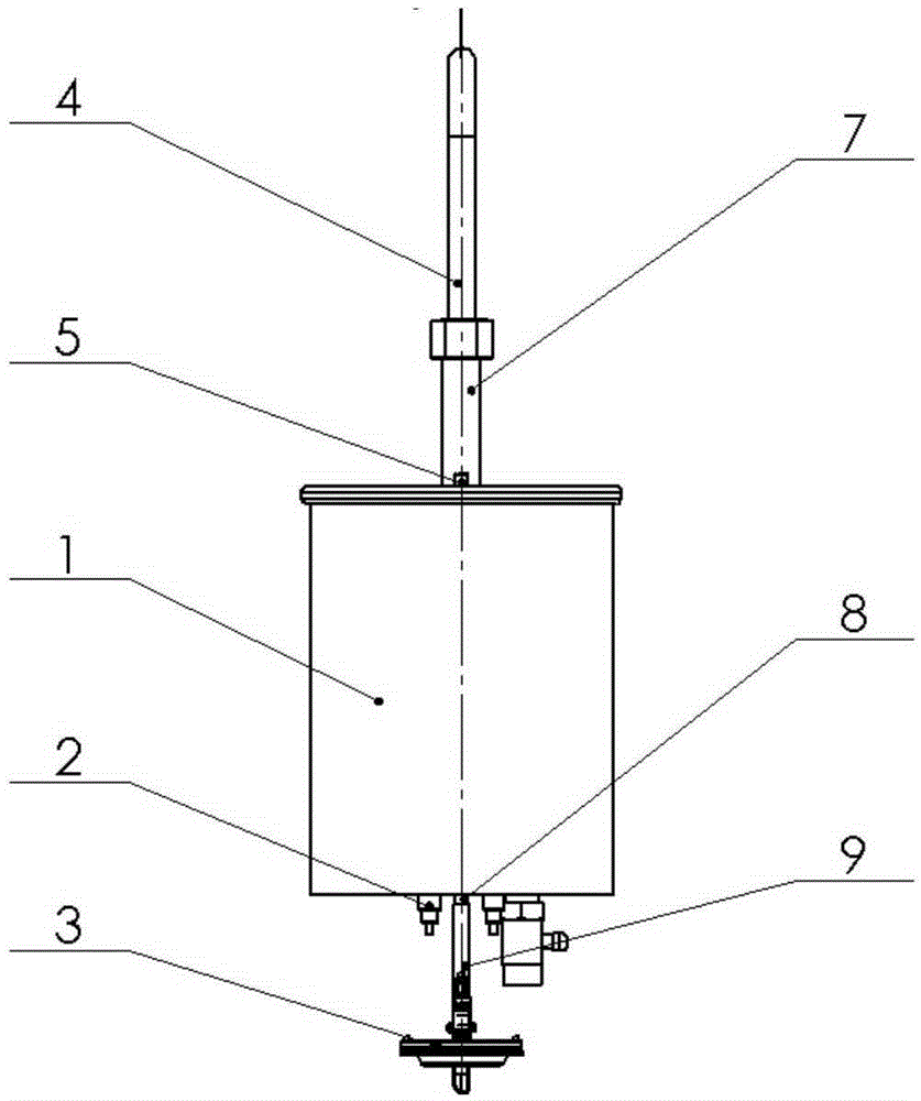
[0046] like Figure 5-8 As shown, the pressure detection controller 3 consists of a disc valve housing 31, a rubber template 32, a mounting ring 33, a mounting frame 34, an adjusting wire seat 35, a shape-retaining load-bearing cap 36, a guide rod 37, a restoring spring 38, Guide pipe 39, water inlet switch 3A, heating switch 3B, switch shaft 3C, adjusting screw 3D, assembly screw 3E, water pipe seat 3F; Cavity 1 is communicated, and the other side of formwork 32 is communicated with atmosphere; The central part of formwork 32 upper surface is provided with conformal load-bearing cap 36, can suppress the deformation of template central part, and undertake formwork pressure; The guide rod 37 is covered with a return spring 38; the pressure detection controller 3 also includes a water inlet switch 3A for controlling the water inlet pipe 4 and a heating switch 3B for controlling the heating element 2 ; Installed on the mounting frame 34 by the switch shaft 3C, the switch contact...

Embodiment 2

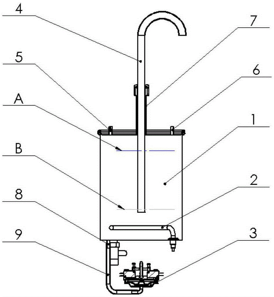
[0048] The drain valve 8 is installed at the bottom of the heating chamber 1; the heating element 2 is installed at the bottom of the heating chamber 1; the water inlet pipe seat 5 can be installed at any position of the heating chamber 1; There is enough space to place the water intake container; the flow-limiting air pipe 6 is installed on the top of the heating chamber. The upper water level A can be set as required.

[0049] like Figure 10 Shown is the outline drawing of a water boiler suitable for municipal water supply with a solenoid valve; a water purifier can be installed in the box below the water tray.

Embodiment 3

[0051] The water inlet control part of above-mentioned water inlet pipe 5 can adopt electromagnetic valve, miniature water pump etc. When the water inlet pipe is connected to a large bucket of water, such as Figure 11 Shown is the situation that is adapted to the water supply of vat water, is the water dispenser that combines water intake with miniature water pump and one-way valve;


PUM


Abstract

A voltage controlled self-overflow electric heating water boiler comprises a heating element, a heating cavity and a water inlet pipe. A water outlet pipe is plugged into the heating cavity from the top of the heating cavity. A limit vent hole is formed in the top of the heating cavity, and the bottom of the heating cavity is connected with a pressure detection controller through a communication pipe. A rubber template of the pressure detection controller is installed at the upper portion of a dish-shaped valve shell. A closed space between the dish-shaped valve shell and the rubber template is communicated with the heating cavity through a communication pipe, and the other surface is communicated with the atmosphere. A guide ejector rod is arranged above the rubber template. A water inlet microswitch and a heating microswitch are triggered through the guide ejector rod. The gravity center of the water boiler is lowered, the effective area of a water catching platform is enlarged, the water outlet height is increased, materials and labor are saved, the failure rate decreases, and people do not need to drink left water. The water boiler adapting to the constantly improved environment is provided for offices, production and even families, a boiling water pump is not used, pressure of municipal water supply is not needed, the structure is simple, the performance is stable, installation is convenient, and the manufacturing cost is low.

Description

technical field [0001] The invention relates to a pressure-controlled self-overflow electric water boiler, which uses the pressure in a heating container to control water intake and heating of the water boiler. Background technique [0002] The traditional water boiler has a large water tank for people to take water conveniently, which stores a considerable amount of boiled water. The oxygen content of this water is greatly reduced after long-term heat preservation and storage, which is not good for people's health; as people's health awareness continues to increase, The stale water in many water boilers is drained every morning; precious water resources are wasted, and storage containers require a lot of high-quality stainless steel. [0003] Existing water boilers are bulky, have a small water receiving platform, need to bend over to fetch water, have an ugly appearance, lack commercialization and humanized design, and are not compatible with the ever-improving quality of ...

Claims


Application Information

Patent Timeline
Patent Type & Authority Patents(China)
IPC IPC(8): F24H9/20
Inventor 何西荣李旭平李志戈
Owner 李旭平
Why Eureka
Try Eureka