
Power battery cover plate

A technology of power battery and cover plate, which is applied in the direction of battery cover/end cover, battery pack parts, battery box/coating, etc., to achieve the effects of enhancing safety, increasing riveting airtightness, and increasing detent torque

Inactive Publication Date: 2014-03-26
SHENZHEN KEDALI IND CO LTD
View PDF5 Cites 8 Cited by
  • Summary
  • Abstract
  • Description
  • Claims
  • Application Information

AI Technical Summary

Problems solved by technology

[0003] In order to solve the problems of the existing battery cover, the purpose of the present invention is to provide a power battery cover that facilitates battery connection and improves battery safety

Method used


Image

  • Power battery cover plate
  • Power battery cover plate
  • Power battery cover plate

Examples


Embodiment Construction

[0022] The present invention will be described in further detail below in conjunction with the embodiments and with reference to the accompanying drawings.

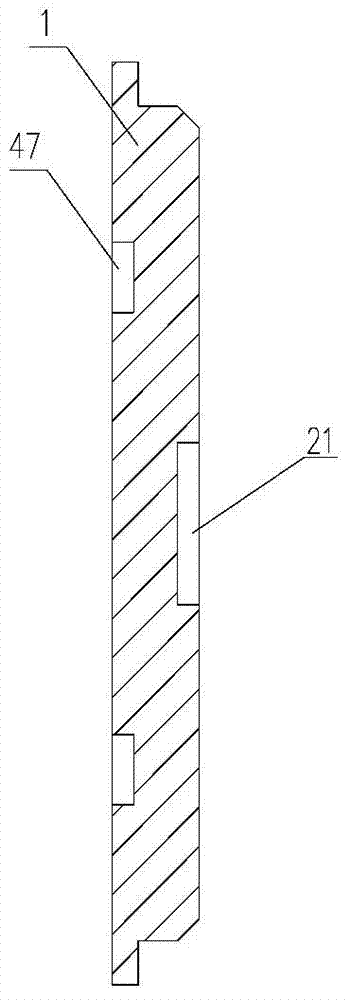
[0023] A power battery cover plate of this embodiment, please refer to Figure 1 to Figure 6 , a power battery cover plate, including a base plate 1, a positive pole 4 and a negative pole 7, the base plate 1 is provided with two pole holes 46 and 72 for respectively passing through the positive pole 4 and the negative pole 7, The ends of the positive pole 4 or the negative pole 7 passing through the substrate 1 are respectively riveted on one end of the positive riveting block 41 or the negative riveting block 71; the other end of the positive riveting block 41 is provided with a positive connecting bolt 43. The other end of the negative electrode riveting block 71 is provided with a negative electrode connecting bolt 73. In this example. The positive column 4 is machined from aluminum, and the negative column 7 is mach...


PUM


Abstract

The invention relates to power batteries, and discloses a power battery cover plate, which includes a base plate, an anode pole and a cathode pole, wherein two pole holes used for penetrating through the anode pole and the cathode pole respectively are formed in the base plate; the anode pole or the cathode pole penetrates through the end part of the base plate and is respectively riveted to one end of an anode riveting pressing block or one end of a cathode riveting pressing block; an anode connecting bolt is arranged at the other end of the anode riveting pressing block; a cathode connecting blot is arranged at the other end of the cathode riveting pressing block. The invention has the advantages that the power battery cover plate facilitates battery connection and improves safety of batteries.

Description

technical field [0001] The invention relates to a power battery, in particular to a power battery cover plate which facilitates battery connection and improves battery safety. Background technique [0002] The power battery is an important part of new energy vehicles. The power battery hinders the development of new energy vehicles. Therefore, the safety and practical performance of the battery are particularly important performance parameters, and the riveting effect of the power battery cover is the key point. , a good riveting effect can increase the safety performance of the battery and the convenience and quickness of assembling the battery into a module, etc., but the riveting parts of the prior art are still difficult to achieve the desired effect in terms of battery safety and single-cell connection. Contents of the invention [0003] In order to solve the problems of the existing battery cover, the purpose of the present invention is to provide a power battery cov...

Claims


Application Information

Patent Timeline
Patent Type & Authority Applications(China)
IPC IPC(8): H01M2/04H01M2/06H01M50/147H01M50/172H01M50/183H01M50/30
CPCH01M50/147H01M50/172H01M50/543Y02E60/10
Inventor 李智辉励建炬
Owner SHENZHEN KEDALI IND CO LTD
Learn More