A wireless sensor network lifetime optimization method for mobile multi-sink nodes

A wireless sensor network and optimization method technology, applied in wireless communication, network topology, advanced technology, etc., can solve problems such as energy holes, limited network survival time, and large network delay

Active Publication Date: 2017-05-10
ZHEJIANG SHUREN UNIV
View PDF2 Cites 0 Cited by
  • Summary
  • Abstract
  • Description
  • Claims
  • Application Information

AI Technical Summary

Problems solved by technology

However, the underwater wireless sensor network has the following problems: there is also the energy hole problem; the water surface gateway must communicate with the underwater sensor node and the sink node, which consumes more energy
The wireless sensor network lifetime optimization method with fixed node positions Assuming that the node positions are fixed, the sensor nodes distributed around the Sink nodes can easily become hub nodes, which receive and forward more neighbor node data and consume less energy. Large, limited network lifetime
No matter how you adjust the algorithm, there will always be unbalanced distribution of energy consumption of nodes in the monitoring area, and the problem of energy holes will appear
Many wireless sensor network survival time optimization methods about the movement of a single sink node only consider moving the sink node to the position of the sensor node to collect data
This method limits the selection range of the sink node's stay position, and the result obtained is a local optimal solution, which has certain limitations.
Since the wireless sensor network survival time optimization method for the movement of a single sink node only considers the movement of one sink node, and the sink node needs to collect the data of all sensor nodes, so its moving path is long and the network delay is large

Method used


Image

  • A wireless sensor network lifetime optimization method for mobile multi-sink nodes
  • A wireless sensor network lifetime optimization method for mobile multi-sink nodes
  • A wireless sensor network lifetime optimization method for mobile multi-sink nodes

Examples


Embodiment approach

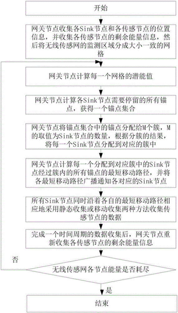
[0085] As another embodiment of the present invention, formula (1-1) can also be used to calculate the potential value of each grid:

[0086]

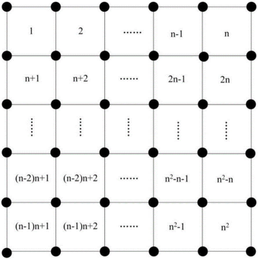
[0087] In formula (1-1), P(v) represents the potential value of grid v, grid v Indicates the grid center of grid v, d vj Represents the sensor node j in the set N(v) to the grid center grid of the grid v v distance, d max Indicates the maximum communication distance of the sensor node, N(v) indicates the grid center grid of the grid v in the monitoring area of ​​the wireless sensor network v The distance does not exceed d max (that is, the set of all sensor nodes within the communication range of one hop). alpha 1 Indicates the distance potential factor, which ranges from 1 to 3, and the preferred empirical value is 2. Equation (1-1) does not consider the remaining energy of sensor nodes, which will cause the imbalance of node energy consumption and shorten the network generation time.

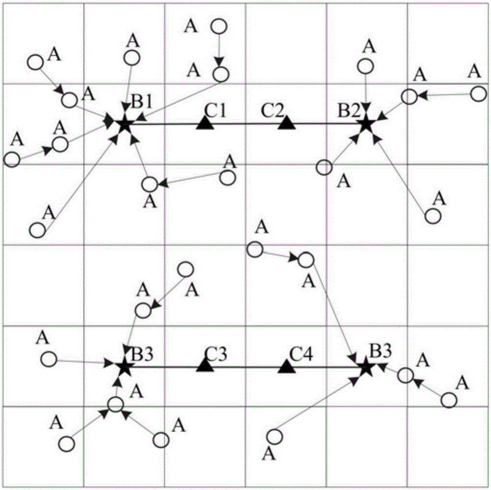
[0088] Step 3: The gateway node calcul...

Embodiment approach

[0089] The specific preferred implementation method of this step is as follows:

[0090] a1) Select the center of the grid with the largest potential value as the current anchor point among all the grids in the monitoring area of ​​the entire wireless sensor, and record the potential value P of the grid where the current anchor point is located * (1), adding the current anchor point to an empty anchor point set P at this time;

[0091] a2) With the current anchor point as the current convergence point, determine all sensor nodes whose minimum transmission hops to the current convergence point do not exceed 2, and all the grids in the maximum communication coverage area of ​​these sensor nodes form a set Q 1 ;According to the method shown in formula (2), the set Q 1 Subtract the potential value P of the grid where the current anchor point is located from the potential value of each grid in * , thus correspondingly get the set Q 1 New potential values ​​for each grid in :

...


PUM


Abstract

The invention discloses an optimization method for the survival time of a multi-Sink-node movement wireless sensor network. The optimization method comprises the steps that (1), a gateway node collects position information of Sink nodes and sensing nodes, and dump energy information of the sensing nodes, and a monitored area is divided into grids of the same size; (2), the potency value of each grid is calculated; (3), all anchor points where the Sink nodes need to remain are calculated to obtain an anchor point set; (4), anchor points in the anchor point set are distributed to M clusters, and the Sink nodes are distributed to the corresponding clusters; (5), the shortest movement path along which the Sink nodes distributed to the corresponding clusters pass through all the anchor points in the clusters is calculated, and is broadcast and informed to the corresponding Sink nodes; (6), all the Sink nodes collect data of the sensing nodes at the same time along the respective shortest movement paths; (7), after data collection of one time period is completed, dump energy information of the sensing nodes is collected again, and if energy of the sensing nodes are used up, the process ends, or, the step (2) is carried out.

Description

technical field [0001] The invention relates to a network survival time optimization method, in particular to a wireless sensor network survival time optimization method in which multiple Sink nodes move. Background technique [0002] Wireless sensor networks (WSNs) usually contain a large number of sensor nodes. These sensor nodes collect various data in the monitoring area, and send the data to the sink node for further processing through multi-hop. They are usually used in the monitoring of indoor / outdoor environment, sanitation and health, electricity, inventory location, factory and process automation, earthquake and structure, and the tracking of targets such as animals, humans, and vehicles, and are increasingly popular in the industry and The attention of academia has enormous potential to enhance and transform how people interact with the world. In wireless sensor networks, the network lifetime is one of the most important indicators to measure the performance of ...

Claims


Application Information

Patent Timeline
Patent Type & Authority Patents(China)
IPC IPC(8): H04W40/10H04W40/20H04W84/18
CPCY02D30/70
Inventor 王章权陈友荣任条娟尉理哲许森
Owner ZHEJIANG SHUREN UNIV
Why Eureka
Try Eureka