Auger bit with highly-spiral land

A technology of twist drill and helical edge, which is applied in the direction of twist drill, etc., can solve the problems of low straightness and position of twist drill, achieve the effect of increasing the length of the margin, increasing the helix angle of the margin, and improving the stability

Active Publication Date: 2014-04-02
SUZHOU AHNO PRECISION CUTTING TECH CO LTD
View PDF6 Cites 9 Cited by
  • Summary
  • Abstract
  • Description
  • Claims
  • Application Information

AI Technical Summary

Problems solved by technology

At present, with the promotion of cemented carbide twist drills, problems such as low straightness and position of twist drill holes are gradually exposed in the process of pursuing high processing efficiency.

Method used


Image

  • Auger bit with highly-spiral land
  • Auger bit with highly-spiral land
  • Auger bit with highly-spiral land

Examples


Embodiment Construction

[0026] The present invention will be further described below in conjunction with the accompanying drawings and embodiments.

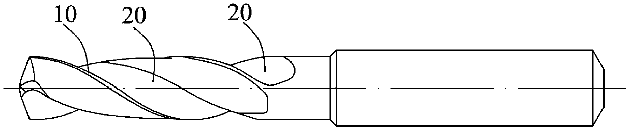
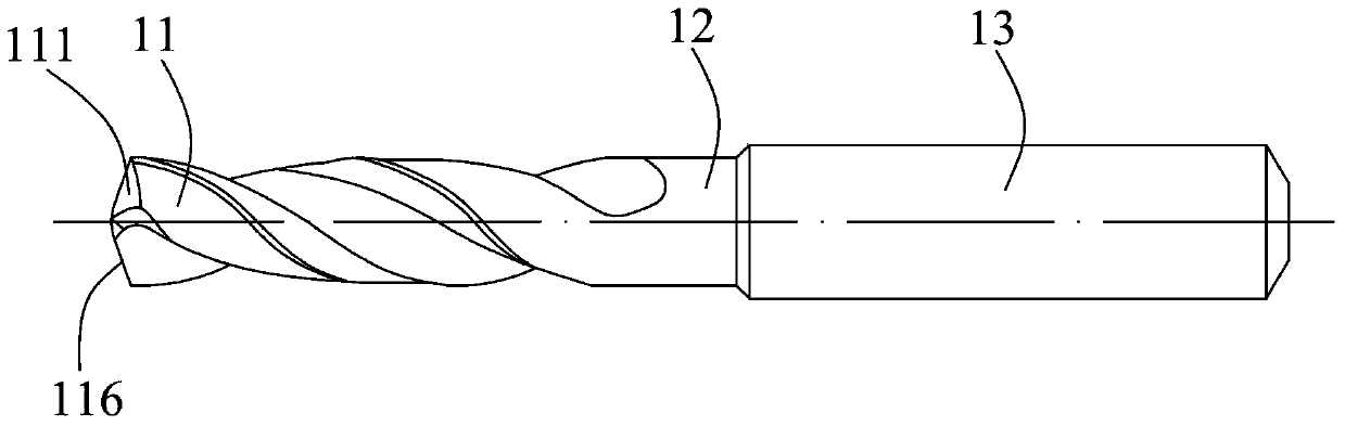
[0027] Such as figure 2 Shown is a twist drill with a high helical margin according to the present invention, which includes a head 11 , a shank 13 and a neck 12 between the head 11 and the shank 13 . The head 11, the neck 12 and the handle 13 are coaxial cylinders centered on the same central axis. The diameter of the shank 13 is greater than the diameter of the neck 12 . The shank 13 is a section of cylinder with high cylindricity, and the external collet clamps the shank 13 to transmit the power of the machine tool, so that the head 11 can rotate to have cutting ability.

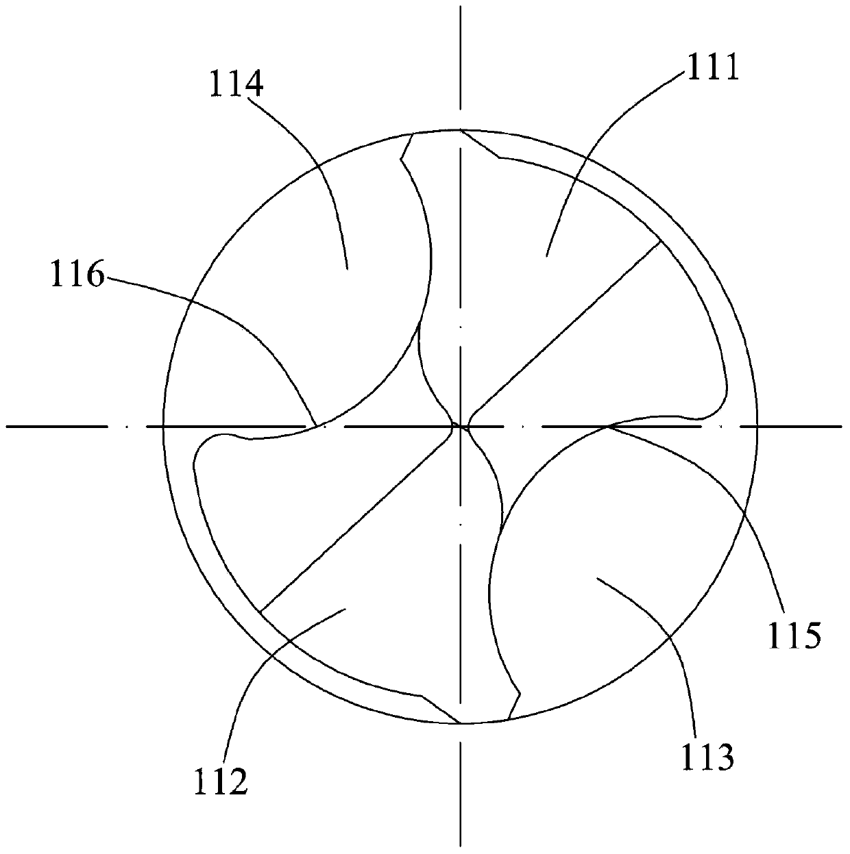
[0028] Such as figure 2 and image 3 As shown, the front end of the head 11 is provided with a first tip 111 and a second tip 112 for drilling. The first tool tip 111 and the second tool tip 112 extend spirally along the circumferential direction with the central axis as the...


PUM


Abstract

The invention discloses an auger bit with a highly-spiral land. The auger bit comprises a head, a stem and a neck between the head and the stem. The head, the neck and the stem are a coaxial cylinder using the same central axis as the center. The front end of the head is provided with a first tool nose and a second tool nose which are used for drilling. The first tool nose and the second tool nose peripherally spirally extends by using the central axis as axis. A first chip groove and a second chip groove are formed between the first tool nose and the second tool nose. A first main cutting edge for drilling is disposed on the first tool nose. A second main cutting edge for drilling is disposed on the second tool nose. The auger bit further comprises a tool back and the highly-spiral land, wherein the highly-spiral land is independent of the first chip groove and the second chip groove and disposed in the middle of the tool back. Due to the fact that the highly-spiral land is independent of the chip grooves, the spiral angle of the land is increased, the length of the land is increased, and stability of the bit during machining is increased.

Description

technical field [0001] The invention relates to a high-efficiency high-speed precision tool, in particular to a high-helical edge-band twist drill bit for high-efficiency hole processing and high-speed processing. Background technique [0002] Please refer to the Chinese patent No. CN101733450A announced on November 14, 2012 for the prior art related to the present invention, which discloses a multifunctional twist drill with a shank, a neck and a working part. The working part includes a guide part and a Cutting part, the cutting part is made up of the main cutting edge and the flank, the center of the cutting part has a small-diameter twist drill extending out, the small-diameter twist drill has a guide part and a cutting part, the cutting part of the small-diameter twist drill is formed by the main The blade, the flank and the chisel edge are provided with a positioning tip at the center of the chisel edge. [0003] Such as figure 1 Shown is an existing twist drill comp...

Claims


Application Information

Patent Timeline
Patent Type & Authority Applications(China)
IPC IPC(8): B23B51/02
CPCB23B51/02
Inventor 刘伟刘刚虞良张静峰
Owner SUZHOU AHNO PRECISION CUTTING TECH CO LTD
Why Eureka
Try Eureka