
Preparation method of throw-away drill and throw-away drill

A discarded drill bit technology, applied in twist drills and other directions, can solve the problems that the height of the cutting blade cannot be too small, the helix angle of the chip flute cannot be achieved, and the cutting blade is prone to shaking. The method is simple and feasible, and the strength is enhanced. The effect of maintaining work performance

Inactive Publication Date: 2014-06-18
东莞艾瑞克精密工具有限公司
View PDF13 Cites 0 Cited by
  • Summary
  • Abstract
  • Description
  • Claims
  • Application Information

AI Technical Summary

Problems solved by technology

[0004] However, there is still a big problem in such a discarded drill bit. Since the cutting blade will be provided with a locking hole for fixing, the height of the cutting blade cannot be too small, which will cause the spiral of the chip flute on the cutting blade. The angle cannot be maximized, the helix angle of the flute is the same as the helix angle of the drill body, which affects the chip removal performance of the drill
Moreover, the bottom of the cutting blade is generally arranged in a rectangular shape, and the groove for accommodating the cutting blade provided on the cutting end of the drill body is also rectangular. When the drill bit is under force, the cutting blade is prone to shaking, which affects the performance of the drill.

Method used


Image

  • Preparation method of throw-away drill and throw-away drill
  • Preparation method of throw-away drill and throw-away drill
  • Preparation method of throw-away drill and throw-away drill

Examples


Embodiment

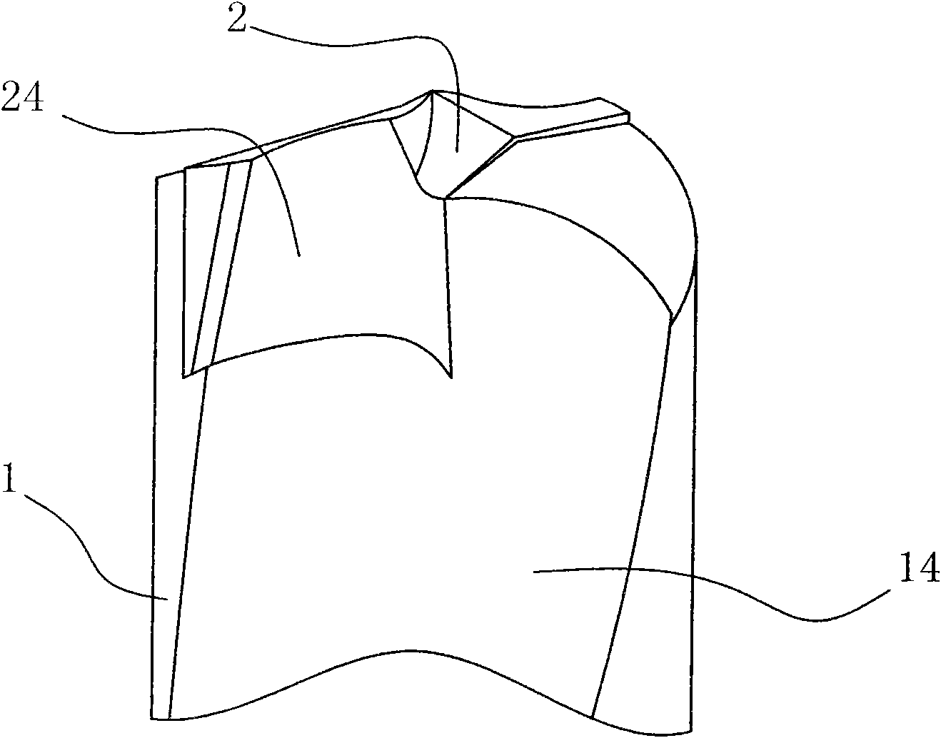
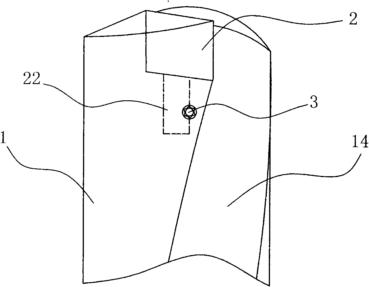
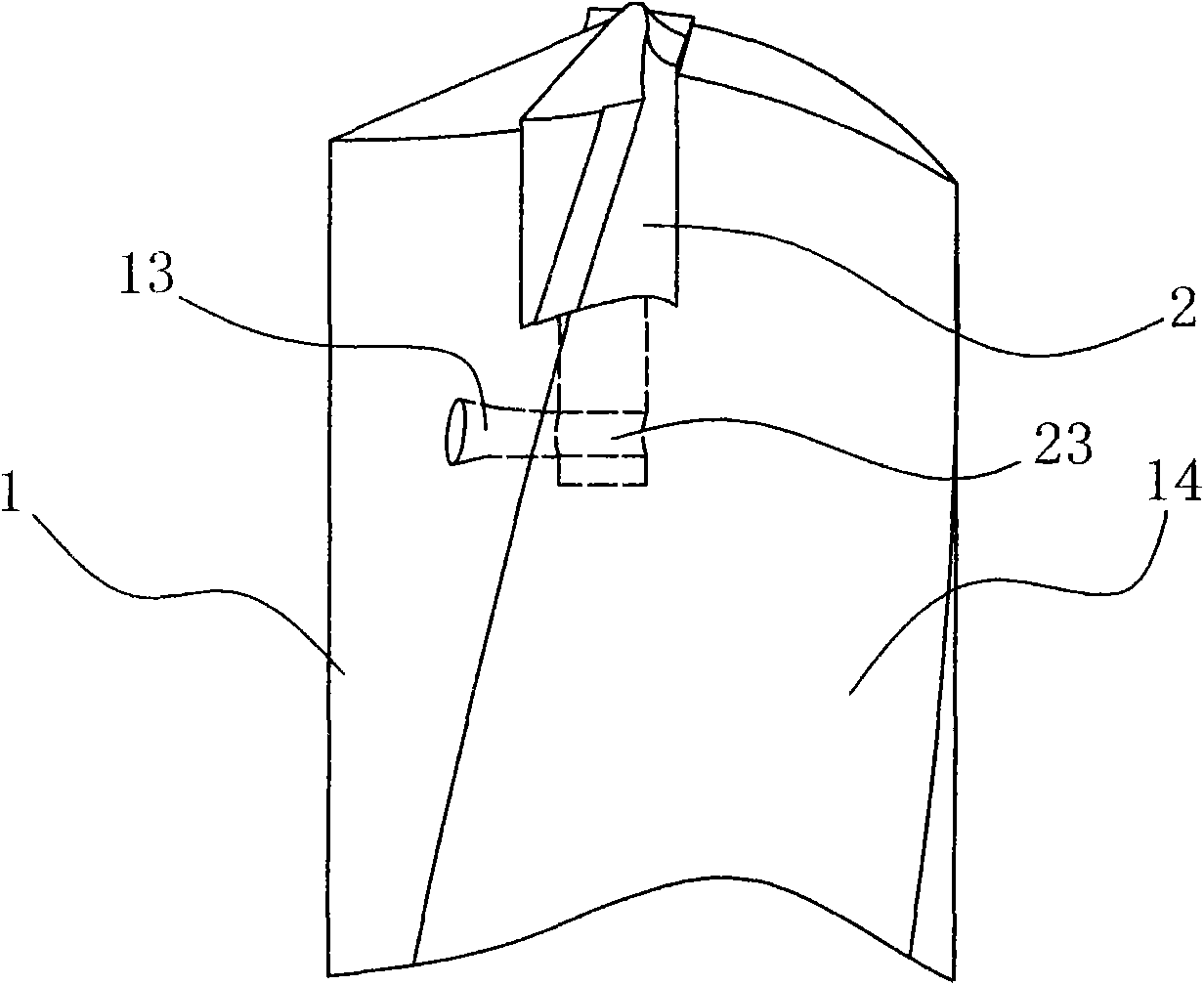
[0032] Example: see Figure 1 to Figure 7 , a method for preparing a discarded drill bit of the present invention, which comprises the following steps:

[0033] (1) Prepare a drill body 1, set a groove 11 horizontally in the middle of the cutting end of the drill body 1, and set a positioning hole 12 at the bottom of the groove 11, and the positioning hole 12 is located on the central axis of the drill body 1 ;

[0034] (2) prepare a cutting blade 2, the cutting blade 2 includes a cutting blade body 21 and a positioning post 22 arranged at the bottom of the cutting blade body 21, the cutting blade body 21 can be inserted into the groove 11 and closely fit, The positioning column 22 is matched with the positioning hole 12;

[0035] (3) Insert the cutting blade 2 into the groove 11, fix the cutter body 21 to the drill body 1 by making structural improvements on the positioning column 22 and the drill body 1, avoiding the The main body 21 is provided with locking holes for fix...


PUM


Abstract

The invention discloses a preparation method of a throw-away drill, which comprises the following steps of: (1) preparing a drill body, transversely arranging a groove at the middle part of the cutting end of the drill body, and arranging a positioning hole on the bottom of the groove, wherein the positioning hole is located on the central axis of the drill body; (2) preparing a cutting blade which comprises a cutting blade body and a positioning column arranged on the bottom of the cutting blade body, wherein the cutting blade body can be inserted into the groove and in tight fit with the groove, and the positioning column is matched with the positioning hole; (3) inserting the cutting blade into the groove, and fixing the cutting blade body on the drill body through improvement of structures of the positioning column and the drill body so that a locking hole used for fixing and arranged on the cutting blade body is dispensed, and further the height of the cutting blade body can be reduced, the helical angle of a chip removing groove arranged on the cutting blade body is increased, and the chip removing capacity is improved. The invention also discloses a throw-away drill.

Description

technical field [0001] The invention relates to a drill bit, in particular to a method for preparing a discarded drill bit and a discarded drill bit prepared by the method. Background technique [0002] In the prior art, commonly used drill bits are generally all manufactured in one piece, the cutting edge and the drill body are connected as one, and the cutting edge is used after being worn during work. Because the manual regrinding of the drill bit can only grind some simple drill shapes, it is difficult to popularize some good and more complex drill shapes, and the drill bits are generally only reground about 10 times, and the rest are not used, resulting in material and money losses. waste. [0003] At present, some discarded drill bits that can replace the cutting working part have appeared in response to this situation. This drill bit includes a drill body and a cutting blade fixed on the cutting end of the drill body. The cutting blade is made of high-performance too...

Claims


Application Information

Patent Timeline
Patent Type & Authority Patents(China)
IPC IPC(8): B23B51/02B23P15/32
Inventor 苏茂均
Owner 东莞艾瑞克精密工具有限公司
Learn More