AI technical title is built by PatSnap AI team. It summarizes the technical point description of the patent document.
A technology of feeder and double twisted dragon, which is applied in the field of heating equipment, can solve the problems of affecting the combustion effect, reducing the combustion rate, and long combustion time, so as to avoid backfire phenomenon, improve combustion efficiency, and smooth the combustion space
Active Publication Date: 2017-01-18
郑文虎
View PDF11 Cites 0 Cited by
Summary
Abstract
Description
Claims
Application Information
AI Technical Summary
This helps you quickly interpret patents by identifying the three key elements:
Problems solved by technology
Method used
Benefits of technology
Problems solved by technology
[0002] Biomass fuel heating equipment uses all waste crops such as straw, rice straw, fuelwood, wood chips, peanut shells, melon seed shells, beet pulp, bark, etc., and is finally made into granules by crushing, mixing, extrusion, drying and other processes. Fuel, the fuel burns for a long time, the temperature of the enhanced combustion furnace is high, and it is economical. At the same time, it has no pollution to the environment, zero emission of CO and zero emission of SO. It is a renewable energy source, recyclable, and can replace wood, coal, and natural gas. Correspondingly, the development of biomass fuel heating equipment is promoted. All kinds of heating equipment are designed with corresponding feeders, because the feeder is directly connected with the combustion chamber. Due to the increase of the temperature and pressure in the combustion chamber during the combustion process, there will be Backfire phenomenon, the fuel in the feeder is ignited, and the fuel in the storage bin is ignited, and the equipment will be burned at the slightest, and a fire accident will occur at the worst. Therefore, the defects of the existing feeder have potential safety hazards. In addition, the combustion chamber The final biomass fuel will coke and adhere to the bottom of the combustion chamber. If it is not treated for a long time, it will affect the combustion effect and reduce the combustion rate, and manual treatment is relatively troublesome.
Method used
Image
Click on the blue label to locate the original text in one second.
Reading with bidirectional positioning of images and text.
Examples
Embodiment Construction
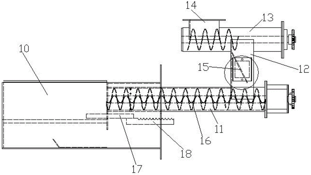
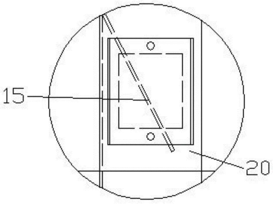
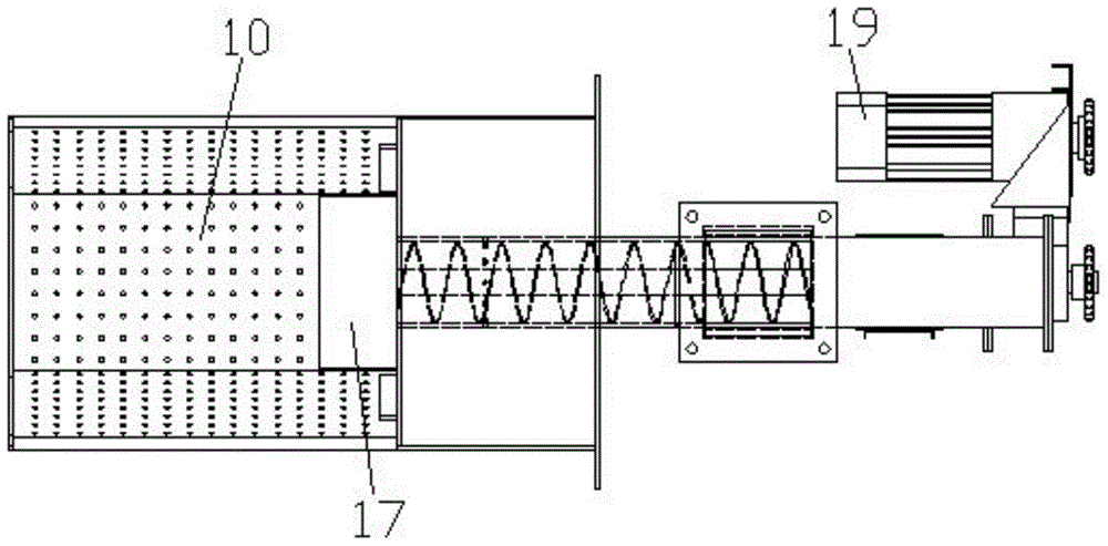
[0016] Below in conjunction with accompanying drawing, the present invention will be further described with specific embodiment, see figure 1 —4: double twisted dragon feeder, including combustion chamber 10 and ignition system, wherein, described combustion chamber 10 side is provided with feeding mechanism, and the specific structure of described feeding mechanism is: described combustion chamber 10 side is provided with feeding mechanism Pipe 11, one end of the feeding pipe 11 communicates with the combustion chamber 10, and the other end is closed. A connecting pipe 12 is arranged on the outer circular surface of the tail of the feeding pipe 11, and a feeding pipe 13 is arranged on the connecting pipe 12. The connecting pipe 12 communicates with the feed pipe 11 and the feed pipe 13, the feed pipe 11 and the feed pipe 13 are provided with a screw push rod 16 inside, and the end is provided with a screw connected to the screw push rod 16. Drive device, drive device comprise...
PUM
Abstract
The invention provides a conveyer with double augers, and belongs to the technical field of heating equipment. The conveyer with the double augers comprises a combustion chamber and an ignition system, wherein a conveying mechanism is arranged on one side of the combustion chamber and specifically comprises a conveying pipe, a connecting pipe, a feeding pipe, a feeding opening and a spiral pushing rod; the conveying pipe is arranged on one side of the combustion chamber; the connecting pipe is arranged at the tail of the conveying pipe; the feeding pipe is arranged on the connecting pipe; the feeding opening is formed in an end of the feeding pipe; the spiral pushing rod is arranged in the conveying pipe and the feeding pipe; a tempering-proof plate is arranged in the connecting pipe; and a slag pushing mechanism is arranged on one side of the combustion chamber and is positioned below the conveying mechanism. Materials are conveyed by the conveying pipe and the feeding pipe which are arranged vertically; the tempering-proof plate is arranged between the conveying pipe and the feeding pipe, so that a tempering phenomenon is avoided, and the safety is improved; and slag in the combustion chamber can be removed by the slag pushing mechanism regularly, the slag can be automatically removed, the problem that cokes are generated easily during combustion and are adhered to the bottom of the combustion chamber is solved, the normal combustion space and smooth ventilation of the combustion chamber are guaranteed, and the combustion efficiency is improved.
Description
technical field [0001] The invention belongs to the technical field of heating equipment, and relates to equipment for burning biomass raw materials to provide heat, in particular to a double auger feeder. Background technique [0002] Biomass fuel heating equipment uses all waste crops such as straw, rice straw, fuelwood, wood chips, peanut shells, melon seed shells, beet pulp, bark, etc., and is finally made into granules by crushing, mixing, extrusion, drying and other processes. Fuel, the fuel burns for a long time, the temperature of the enhanced combustion furnace is high, and it is economical. At the same time, it has no pollution to the environment, zero emission of CO and zero emission of SO. It is a renewable energy source, recyclable, and can replace wood, coal, and natural gas. Correspondingly, the development of biomass fuel heating equipment is promoted. All kinds of heating equipment are designed with corresponding feeders, because the feeder is directly conne...
Claims
Application Information
Patent Timeline
Application Date:The date an application was filed.
Publication Date:The date a patent or application was officially published.
First Publication Date:The earliest publication date of a patent with the same application number.
Issue Date:Publication date of the patent grant document.
PCT Entry Date:The Entry date of PCT National Phase.
Estimated Expiry Date:The statutory expiry date of a patent right according to the Patent Law, and it is the longest term of protection that the patent right can achieve without the termination of the patent right due to other reasons(Term extension factor has been taken into account ).
Invalid Date:Actual expiry date is based on effective date or publication date of legal transaction data of invalid patent.

