
Building sample rate independent timing diagrams using digital edge averaging

An averaging and edge technology, applied in digital variable display, digital transmission system, digital variable/waveform display, etc.

Inactive Publication Date: 2014-04-02
TEKTRONIX INC
View PDF5 Cites 0 Cited by
  • Summary
  • Abstract
  • Description
  • Claims
  • Application Information

AI Technical Summary

Problems solved by technology

However, the situation is not always ideal

Method used


Image

  • Building sample rate independent timing diagrams using digital edge averaging
  • Building sample rate independent timing diagrams using digital edge averaging
  • Building sample rate independent timing diagrams using digital edge averaging

Examples


Embodiment Construction

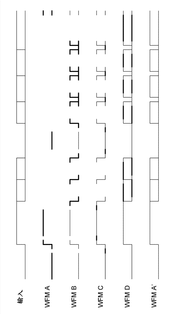
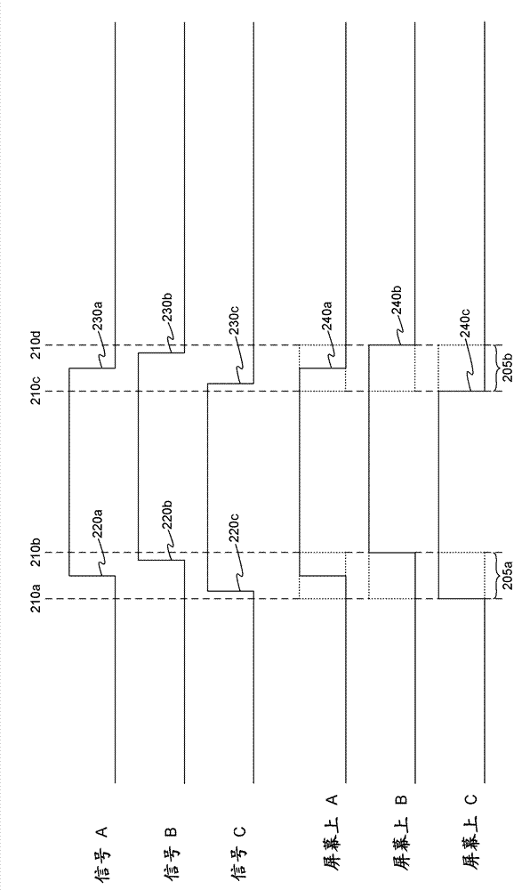
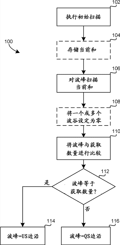
[0012] In the current system, the digital edge average (DEA) of any single transition means that it can only be calculated if the edge appears within each repeated DEA aperture. Through conventional methods, the tested signal has many opportunities to synchronize, but it is not uniformly synchronized (US). This requires the quasi-synchronous (QS) edge type concept described below.

[0013] QS edges as used herein generally refer to edges that appear in the DEA aperture but do not appear in each repeated acquisition. The data bus, the stroboscope whose width is a clock whose width changes in number, and the edge of a clock whose number changes according to the trigger event are all examples of edge events that are conventionally synchronized with the trigger event (for example, they can all be based on the same system clock ), but in the DEA sense, it is only QS.

[0014] Digital Edge Mapping (DEM) usually uses repeated and directional DEA operations to resolve QS edges and uses t...


PUM


Abstract

The invention relates to building sample rate independent timing diagrams using digital edge averaging. A method can include receiving an input signal having multiple signal edges, performing an initial scan of the input signal to identify peaks corresponding to the signal edges, and determining whether each peak is a Uniformly Synchronous (US) edge or a Quasi-Synchronous (QS) edge. The method can also include generating a final waveform and displaying the final waveform on a display device.

Description

Background technique [0001] Digital acquisition devices such as the Tektronix TLA7000 logic analyzer enable electrical engineers to measure the signals generated by the digital systems they design. The research laboratory uses digital acquisition devices to observe the correctness of timing and signal density in the microprocessor, memory, bus, and other components of the digital system. The acquisition device plays an important role in continuing to promote the development of the electronics industry. [0002] The digital acquisition device generally displays the sensed signal in a steeply rising or falling staircase form. The rise from "off" to "on" and the fall from "on" to "off" are usually synchronized with the clock cycle in the system under test, and the transition from one state to another is visually represented as vertical edge. It is useful to distinguish the clock of the system under test from the clock of the digital acquisition device. [0003] In order to provide ...

Claims


Application Information

Patent Timeline
Patent Type & Authority Applications(China)
IPC IPC(8): G01R13/02
CPCG01R13/02G01R13/00H03K5/1532H04L1/00H04L1/205
Inventor J.D.克莱姆
Owner TEKTRONIX INC
Learn More