Connector

A connector and retainer technology, which is applied in the direction of connection, parts of the connection device, fixed/insulated contact members, etc., can solve the problem that the mating operation cannot be carried out smoothly.

Active Publication Date: 2014-04-02
SUMITOMO WIRING SYST LTD
View PDF5 Cites 9 Cited by
  • Summary
  • Abstract
  • Description
  • Claims
  • Application Information

AI Technical Summary

Problems solved by technology

As a result, even after the locking piece is accommodated in the locking piece accommodating portion, the portion of the locking piece accommodating portion is slightly recessed from both side surfaces of the connector housing. , there is a case where the mating operation cannot be smoothly carried out due to the hooking of the other side housing on the locking piece accommodating part, etc.
[0011] In order to solve the above-mentioned problems, it is conceivable to form locking piece accommodating portions on the inside of side walls located at both ends in the width direction of the connector housing, and to protect the locking pieces accommodated in the locking piece accommodating portions by the side walls of the connector housing, However, it is necessary to provide a bending space on the inner side of the side wall to allow elastic deformation of the locking piece, so that the size of the connector housing in the width direction is increased.

Method used


Image

  • Connector
  • Connector
  • Connector

Examples


Embodiment approach 1

[0038] refer to Figure 1 to Figure 10 Embodiment 1 of the present invention will be described.

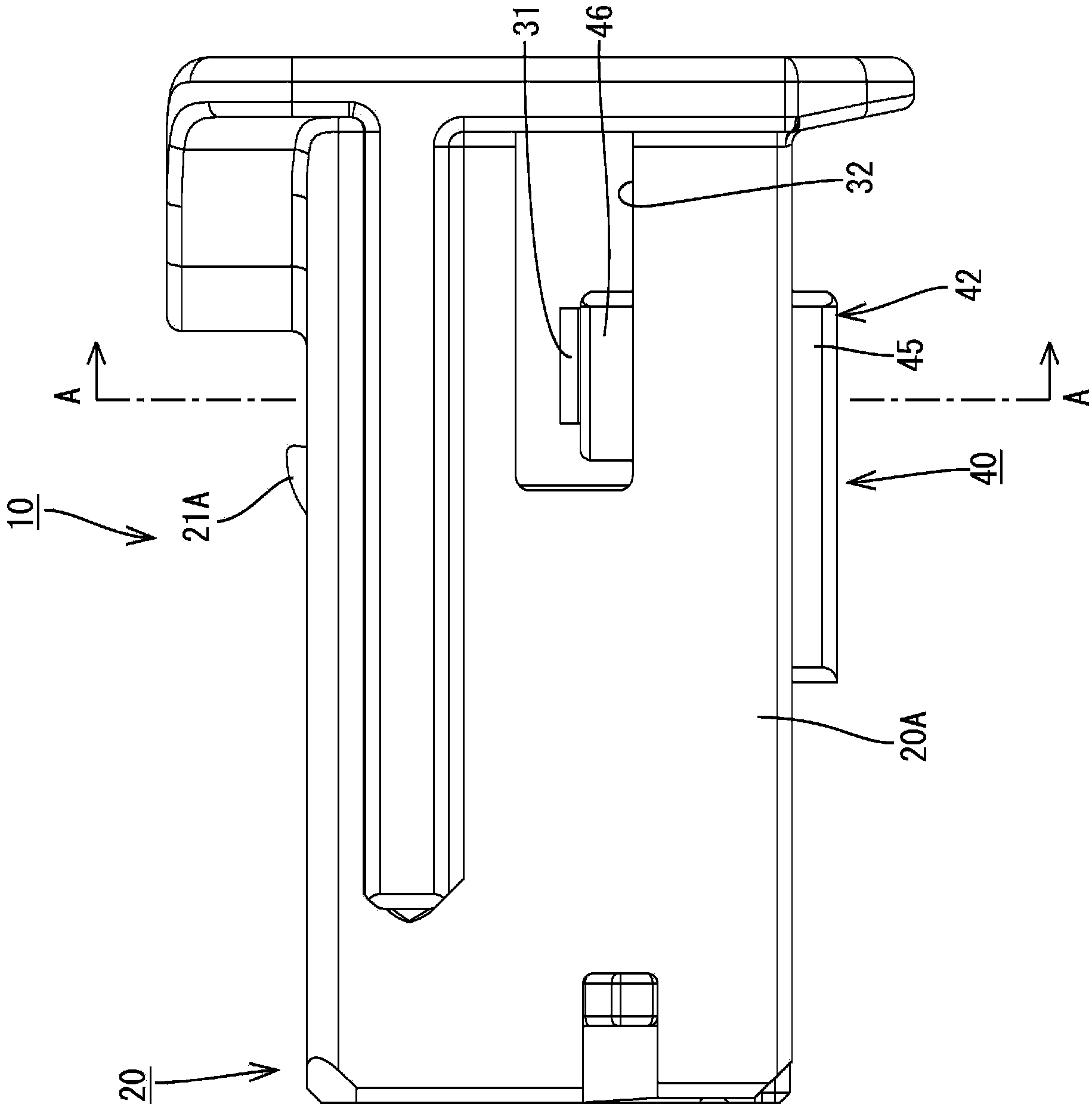
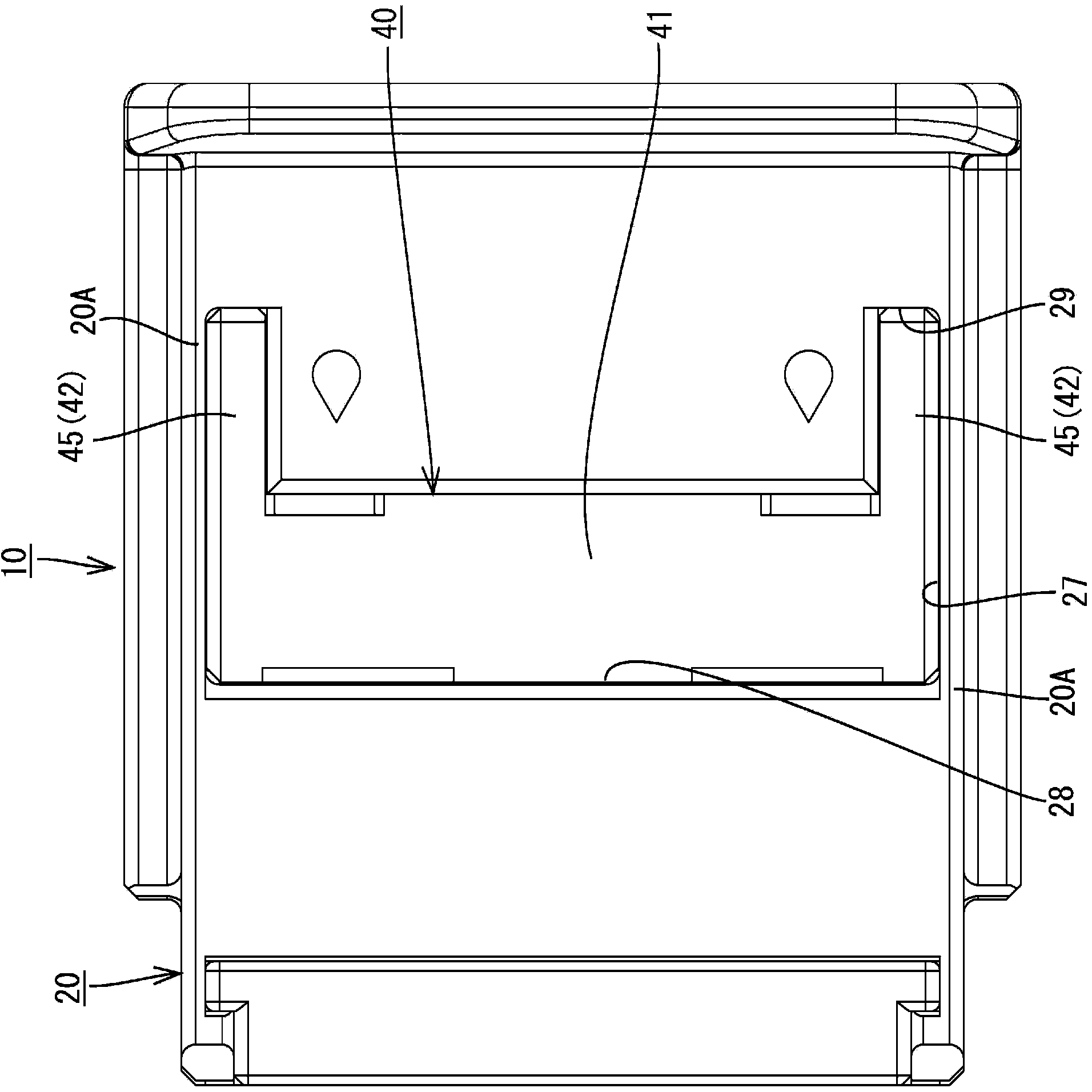
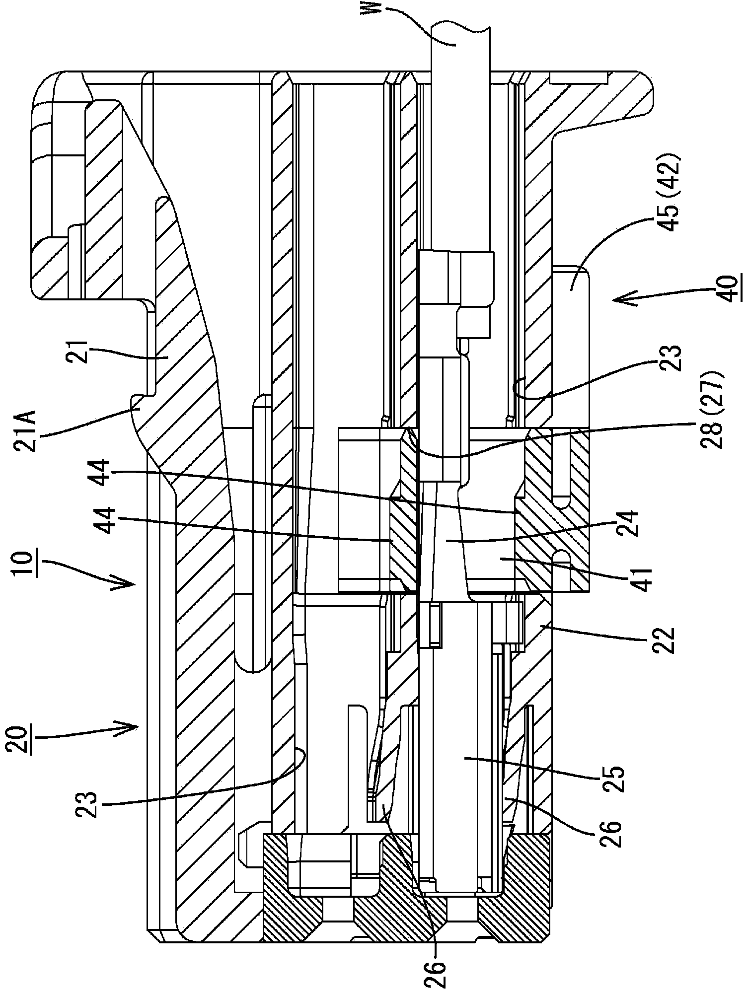
[0039] This embodiment shows a connector 10 as an example, and includes a synthetic resin female housing (an example of the “connector housing” of the present invention) 20 , which can be fitted into a housing not shown in the male housing. and a synthetic resin retainer 40 for preventing the female terminal (an example of the “terminal fitting” of the present invention) 24 housed in the female housing 20 from falling out.

[0040] Such as figure 1 and image 3 As shown, the female-side housing 20 is generally formed in a block shape that is longitudinally long in the front-rear direction. A lock arm 21 extending cantilevered from the front toward the rear is formed on the upper portion of the female housing 20 . The lock arm 21 is formed to be elastically deformable in the vertical direction, and a locking protrusion 21A is formed on the upper surface of the lock arm 21 to be...

Embodiment approach 2

[0078] Next, refer to Figure 11 and Figure 12 Embodiment 2 of the present invention will be described.

[0079] Embodiment 2 is obtained by changing the shape of the lock piece 46 of the retainer 40 in Embodiment 1. Since the configuration, function, and effect common to the above-mentioned embodiment are repeated, description thereof will be omitted. Moreover, the same code|symbol is attached|subjected to the same structure as the above-mentioned embodiment.

[0080] In the retainer 140 according to the second embodiment, the detachment prevention protrusion 150 is formed on the outer surface of the lock piece 146 of the lock plate 142 in the width direction. The detachment prevention protrusion 150 extends outward in the width direction from the locking piece 146 , and is formed to approach the locking piece 146 as it extends upward from the outer end portion thereof, and is held in a state where the retainer 140 is held by the female side housing 20 . The bottom is acc...


PUM


Abstract

A connector (10) comprises: a female-side housing (20) that houses a female terminal (24); and a retainer (40) that has a pair of lock pieces (46), the lock pieces being provided on the respective ends of the retainer in the width direction and being elastically deformable toward the outside in the width direction. The connector (10) is characterized in that: the female-side housing (20) has lock-piece housing sections (29) formed on the inner side of the respective side walls (20A) of the female-side housing (20), the lock-piece housing sections (29) housing the respective lock pieces (46); on the inner surface of each lock-piece housing section (29) on the inner side in the width direction are formed a temporary latching projection (30) and a permanent latching projection (31) over which the lock piece (46) moves by deforming elastically and onto which the lock piece latches by elastically returning to the original state thereof; and a through hole (32) is formed so as to penetrate each side wall (20A) of the female-side housing (20), the through holes (32) allowing the elastic deformation of the respective lock pieces (46).

Description

technical field [0001] The present invention relates to a connector provided with a retainer. Background technique [0002] Conventionally, a connector described in the following Patent Document 1 is known as a connector provided with a retainer for preventing a terminal fitting accommodated in a connector housing from falling out. [0003] The retainer is provided with: a fall-off preventing portion inserted into a retainer insertion hole provided at the bottom of the connector housing to prevent the terminal fitting from falling out; and a pair of locking pieces provided on both sides in the width direction of the fall-off preventing portion It can be elastically deformed outward in the width direction. [0004] A pair of locking pieces are formed so as to be respectively accommodated in locking piece accommodating portions provided on both sides in the width direction of the connector housing, and on the other hand, the locking piece accommodating portions are formed ope...

Claims


Application Information

Patent Timeline
Patent Type & Authority Applications(China)
IPC IPC(8): H01R13/42
CPCH01R13/4223H01R13/4362
Inventor 谷川直孝今井裕次郎
Owner SUMITOMO WIRING SYST LTD
Why Eureka
Try Eureka