U-shaped plug board stamping die and U-shaped plug board stamping method

A stamping die and inserting plate technology, which is applied to the stamping of U-shaped inserting plates and the field of U-shaped inserting plate stamping dies, can solve the problems of wasting steel plates, etc., and achieve the effects of ensuring accuracy, improving the ease of processing, and increasing the difficulty

Inactive Publication Date: 2014-04-09
STATE GRID CORP OF CHINA +4
View PDF8 Cites 2 Cited by
  • Summary
  • Abstract
  • Description
  • Claims
  • Application Information

AI Technical Summary

Problems solved by technology

[0004] The technical problem to be solved by the present invention lies in the problem that a certain amount of steel plates need to be wasted after the existing U-shaped inserting plate stamping die stamps the steel plate, and a U-shaped inserting plate stamping die is provided for this problem, and the specific technical solution is :

Method used


Image

  • U-shaped plug board stamping die and U-shaped plug board stamping method
  • U-shaped plug board stamping die and U-shaped plug board stamping method
  • U-shaped plug board stamping die and U-shaped plug board stamping method

Examples


Embodiment 1

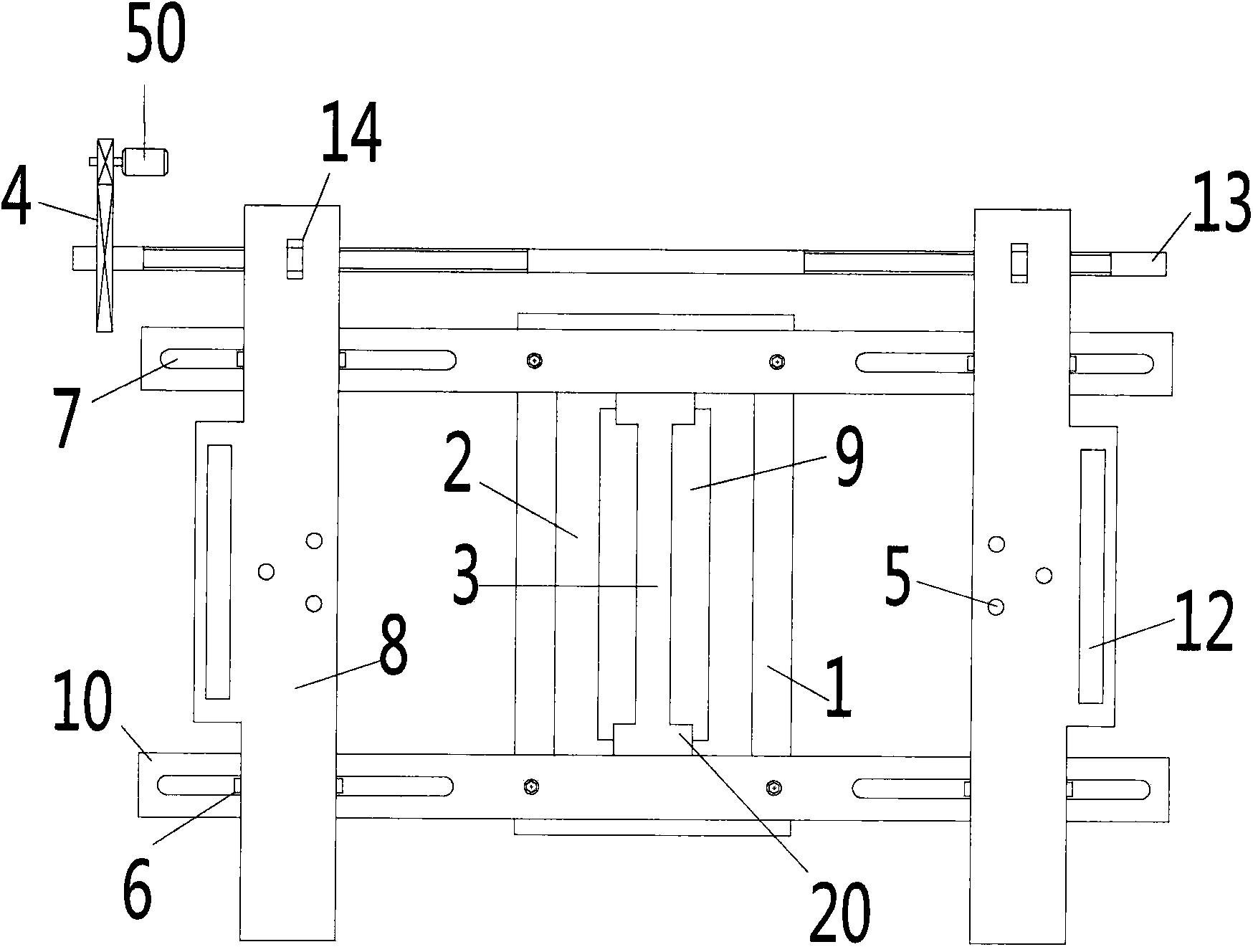
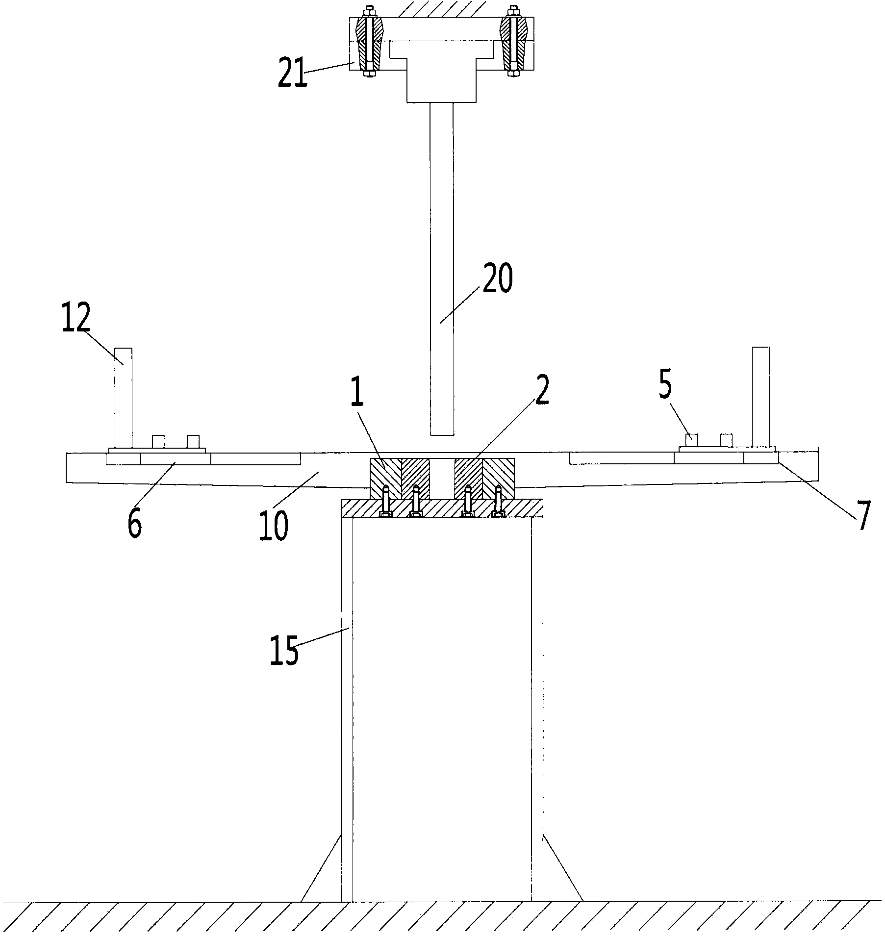
[0039] See Figure 1 to Figure 4 , a U-shaped punching plate stamping die, comprising a lower die support frame 15, a lower die 2 provided with a stamping through hole 9 in the middle, a lower die sleeve 1 set on the lower die 2, an upper die and a positioning part, the lower die 2 and The lower die sets 1 are all fixed on the lower die support frame 15 by bolts, and the top lateral sides of the stamping through hole 9 are provided with 90° arc chamfers 30 .

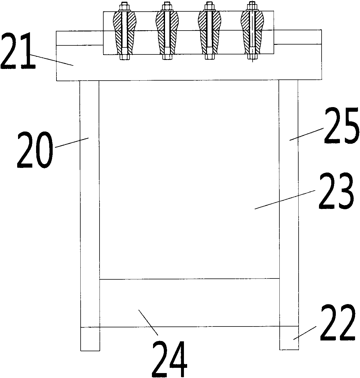
[0040] Upper die comprises the punch 3 that is made up of punch end 24 and punch body 23, two clamping arms 20 and the upper die seat 21 of fixed punch 3 and two clamping arms 20, and clamping arm 20 comprises clamping The clamping section 25 at both ends of the punch 3 and the resisting section 22 protruding from the punch end 24 and abutting against the steel plate during stamping are composed. The punch end 24 and the punch body 23 are separate structures and are connected by bolts. When the punch 3 needs to be repla...

Embodiment 2

[0045] A kind of stamping method of U-shaped flashboard, the method has used the U-shaped flashboard stamping die described in embodiment 1, comprises:

[0046] 1. Use Q345B or Q235B carbon structural steel with a thickness of 8mm-14mm as the raw material, first cut into the steel plate required for punching U-shaped insert plate, and then open three on both sides of the steel plate and position on the moving plate 8 The positioning hole corresponding to the pin 5;

[0047] 2. Make sure the thickness of the U-shaped plate is K, then loosen the bolts between the punch end 24 and the punch body 23, replace the replaced punch end 24, and then re-fix with the bolts so that the replaced punch The thickness D of the head end 24 is equal to the size of the opening after the U-shaped board is formed;

[0048] 3. The width of the punched through hole 9 is set to E, and the radius of the 90° arc chamfer 30 on both sides of the top of the punched through hole 9 is set to R; The total g...


PUM

PropertyMeasurementUnit
radiusaaaaaaaaaa
widthaaaaaaaaaa
thicknessaaaaaaaaaa

Abstract

The invention belongs to the technical field of die devices, and relates to a U-shaped plug board stamping die aims to solve the problem that some steel plates are wasted after steel plates are stamped through an existing U-shaped plug board stamping die. The U-shaped plug board stamping die comprises an upper die and a lower die with a stamping through hole in the middle portion. The U-shaped plug board stamping die further comprises a locating portion which comprises two moving plates which are symmetrically arranged on the two horizontal sides of the stamping through hole and coplanar with or parallel with the lower die, and the two moving plates are both provided with locating pins. The invention further provides a U-shaped plug board stamping method. Through the technical scheme, the technical problems can be effectively solved.

Description

technical field [0001] The invention belongs to the technical field of mold equipment, and relates to a stamping die for a U-shaped board. The invention also provides a stamping method for a U-shaped board. As a special case, the U-shaped board is a U-shaped board with two arms. Shaped inserts, which can be used to connect many sections of steel pipe towers. Background technique [0002] Many mechanical structures use U-shaped inserts. For example, steel pipe towers have their own unique structural forms. Many sections of oblique materials are used as steel pipe structures. The connection methods are different, including C-shaped inserts, cross inserts, and U-shaped inserts. The first two types of plug-in boards are easy to process, while the processing of U-shaped plug-in boards has always been a difficult point. [0003] At present, the U-shaped inserting plate is generally completed by stamping the steel plate with a stamping die. Usually, the stamping die includes an up...

Claims


Application Information

Patent Timeline
Patent Type & Authority Applications(China)
IPC IPC(8): B21D37/10B21D35/00
Inventor 戴刚平王洪王淑红
Owner STATE GRID CORP OF CHINA
Why Eureka
Try Eureka