Noise monitoring system for carrier-rocket launch fuel-gas flows

A launch vehicle and noise monitoring technology, which is applied in measuring devices, measuring ultrasonic/sonic/infrasonic waves, instruments, etc., can solve the problem of inability to systematically and finely evaluate the influence of the rocket body and launch system, limited measuring points, gas flow noise testing, Difficult to analyze

Active Publication Date: 2014-04-09
BEIJING INST OF SPACE LAUNCH TECH +1
View PDF3 Cites 5 Cited by
  • Summary
  • Abstract
  • Description
  • Claims
  • Application Information

AI Technical Summary

Problems solved by technology

[0003] At present, the noise monitoring of the rocket launch gas flow mainly relies on the structural conditions of the launch system of the launch vehicle. Limited measuring points are arranged on the launch system structure to test the noise parameters of the special position. This test is subject to the structural conditions of the launch system (such as the structural conditions of the platform and service tower). Due to limitations, the noise parameters of the test are often difficult to reflect the noise characteristics of the rocket launch gas flow. Under some conditions, the noise parameters are distorted due to the severe interference of the structural conditions of the launch system. Due to the dynamic change law of the position of the sound source, it is impossible to systematically and finely evaluate the influence of the rocket body and the launch system on the gas flow noise, and the current noise monitoring method is only suitable for the detection and evaluation of the gas f...

Method used


Image

  • Noise monitoring system for carrier-rocket launch fuel-gas flows
  • Noise monitoring system for carrier-rocket launch fuel-gas flows
  • Noise monitoring system for carrier-rocket launch fuel-gas flows

Examples


Embodiment Construction

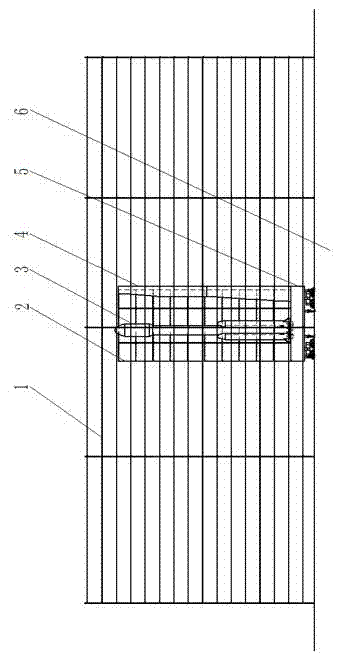
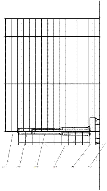
[0017] refer to Figure 1-Figure 8 , the launch vehicle launch system is located on site 6. The launch vehicle gas flow noise monitoring system is mainly constructed based on the launch system conditions, especially the structural scale of the launch system. Two sets of test array devices are used to realize the refined monitoring of the launch vehicle gas flow noise. One of the two sets of test array devices is a far-field test array device 1 , and the other is a near-field test array device 2 .

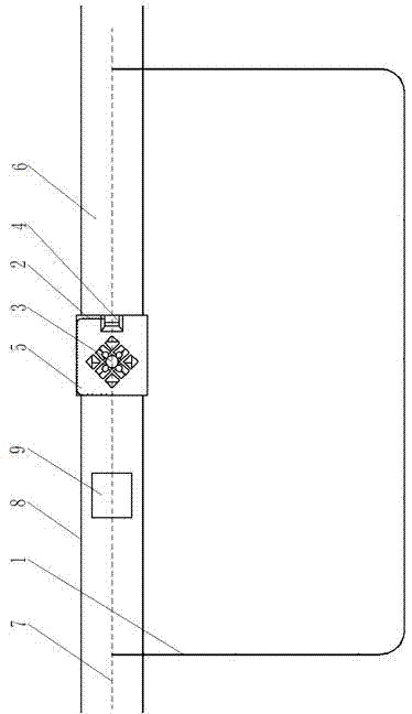
[0018] The far-field test array 1 is mainly used to test the dynamic distribution and change law of the noise source of the launch system during the entire launch process of the launch vehicle, especially the high-intensity sound source, and is suitable for monitoring the entire launch system, especially the launch platform 5, the launch site diversion groove and other position equipment, facility structures and openings (respectively in image 3 Shows the diversion tank outlet 9,...


PUM


Abstract

The invention discloses a noise monitoring system core for carrier-rocket launch fuel-gas flows. The system includes a near-field noise test array device and a far-field noise test array device. The near-field and far-field noise test array devices both use a carrier-rocket body as a symmetrical center to form n-shaped noise test grid nets. Series and evenly distributed array-type noise test arrays are installed through the n-shaped noise test grid nets, wherein the near-field n-shaped noise test grid net uses the outer edge of a launch platform mesa as the contour and includes vertical-rod groups which are vertically and uniformly distributed and installed on the launch platform mesa and cross-bar groups which are horizontally and evenly distributed and installed on the platform-mesa vertical-rod groups. The far-field n-shaped noise test grid net uses a launch platform and launch-field diversion-trench entrance and exit as reference outline dimensions and includes vertical-rod groups which are vertically and evenly distributed and installed on a launch level ground and cross-bar groups which are horizontally and evenly distributed and installed on the level-ground vertical-rod groups. The near-field n-shaped noise test grid net and the far-field n-shaped noise test grid net are placed to be facing each other and use each other as a reference and complement.

Description

technical field [0001] The invention relates to the field of rocket launch, in particular to a system for monitoring the noise of the launch gas flow of a launch vehicle. Background technique [0002] The impact of rocket launch gas flow on the noise of the rocket and the launch system has always been a concern in the fields of rocket launch technology research and development, launch system special equipment development, rocket special noise control, etc. These fields have invested heavily in special noise control technologies and products. Principle and verification research. A very important task in related research is to detect and evaluate the noise parameters of the rocket launch gas flow field. For this reason, many simple or systematic detection methods have been proposed to adapt to different technical forms of rocket launch noise sources and propagation environments. . [0003] At present, the noise monitoring of the rocket launch gas flow mainly relies on the str...

Claims


Application Information

Patent Timeline
IPC IPC(8): G01H17/00
Inventor 陈劲松贾延奎曾玲芳王明华杭立杰
Owner BEIJING INST OF SPACE LAUNCH TECH
Why Eureka
Try Eureka