Spot welding tooling of machine body of press machine and spot welding method employing spot welding tooling

A press and body technology, applied in the field of spot welding tooling for press body, can solve the problems of long welding time, large error, large workload, etc., to reduce the difficulty of spot welding process, improve the efficiency of spot welding and spot welding Accuracy, saving spot welding man-hours

Active Publication Date: 2014-04-16
YANGLI GRP CORP LTD
View PDF15 Cites 3 Cited by
  • Summary
  • Abstract
  • Description
  • Claims
  • Application Information

AI Technical Summary

Problems solved by technology

[0003] In the spot welding process of the press machine body in the prior art, it is necessary to manually control the welding size and accuracy by using various measuring tools and measuring blocks. It is also necessary to add welding process straps during the welding process and remove them after welding. The operation is difficult and Disadvantages such as long welding time, heavy workload, and large errors
Take the spot welding of the fuselage of an ordinary 80T open press as an example, the spot welding process takes 10~12 hours, and the welding error reaches 5~8mm

Method used


Image

  • Spot welding tooling of machine body of press machine and spot welding method employing spot welding tooling
  • Spot welding tooling of machine body of press machine and spot welding method employing spot welding tooling
  • Spot welding tooling of machine body of press machine and spot welding method employing spot welding tooling

Examples


Embodiment Construction

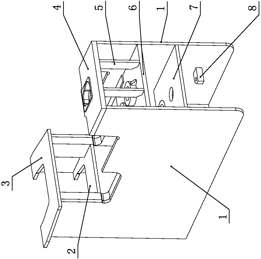
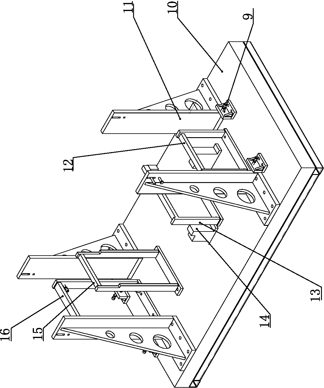
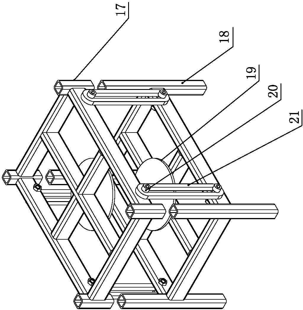
[0024] Such as figure 2 — Figure 4 Shown is the press body spot welding tooling of the present invention, including a spot welding workbench 10 arranged horizontally, and the left and right sides of the spot welding workbench 10 are oppositely provided with main baffles 11 for positioning the left and right fuselage main boards 1 from the outside , the inner sides of the main baffles 11 on the left and right sides are respectively provided with a bracket one 12 and a bracket three 15 for positioning the main boards 1 of the fuselage from the inside, spot welding of the front end of the main baffle 11 at the front end and the rear end of the main baffle 11 at the rear end The workbench 10 is respectively provided with limit stops 9 for positioning the front and rear positions of the two fuselage main boards 1, and the main baffle plate 10, support one 12, support three 15 and limit stop 9 are respectively provided with a position for jacking machine. The adjusting bolt of b...


PUM


Abstract

The invention relates to the field of welding process devices, and in particular relates to spot welding tooling with a simple structure and high spot welding efficiency for the machine body of a press machine and a spot welding method employing the spot welding tooling. The spot welding tooling comprises spot welding workbenches, wherein main baffle plates used for positioning two main plates of the machine body from the outer side are oppositely arranged on the left side and the right side of the spot welding workbenches; a bracket 1 and a bracket 3 which are used for positioning the two main plates of the machine body from the inner side are respectively arranged on the inner sides of the two main baffle plates; limiting stoppers are respectively arranged on the spot welding workbenches of the front end of the main baffle plate at the front end and the rear end of the main baffle plate at the rear end; adjusting bolts used for tightening the main plates of the machine body are respectively and correspondingly arranged on the main baffle plates, the bracket 1, the bracket 3 and the limiting stoppers; a bracket 2 as high as the bracket 1 is arranged on the front side of the bracket 1 side by side; the bracket 1 and the bracket 2 are used for supporting and positioning a rear drive plate; an adjusting bracket with an adjustable height is arranged on the rear drive plate; a bracket 4 as high as the bracket 3 is arranged on the front side of the bracket 3 side by side; the bracket 3 and the bracket 4 are used for supporting a workbench sliding plate; a clutch overlapping bracket is also arranged on each spot welding workbench.

Description

technical field [0001] The invention relates to the field of welding process devices, in particular to a spot welding tool for a press fuselage and a spot welding method using the tool. Background technique [0002] The fuselage is a basic part of the press. In order to facilitate the customization of the size and parameters of the press, the fuselage of most presses adopts a steel plate welded structure. The whole welded fuselage can be split into several steel plates of different thickness and shape, such as figure 1 As mentioned above, it mainly includes two fuselage main boards parallel to the left and right. The rear side between the main boards of the fuselage is respectively fixed with a rear transmission plate, a rear support plate and a front support plate from bottom to top, and a top rib is vertically fixed between the rear support plate and the front support plate, and one of the bottom of the rear transmission plate The inner side of the fuselage main board is...

Claims


Application Information

Patent Timeline
Patent Type & Authority Applications(China)
IPC IPC(8): B23K37/04B23K37/047
CPCB23K37/0435
Inventor 詹俊勇黄加飞吴希牛瑞霞
Owner YANGLI GRP CORP LTD
Why Eureka
Try Eureka