Auger convenient in seaming

A welding and mounting plate technology, applied in packaging and other directions, can solve the problems of wrong sides, prone to cracks, unreliable welding of auger blades, etc., and achieves the effects of reliable installation, enhanced fastening force, and simple structure.

Active Publication Date: 2014-04-16
安徽顺利生物有限公司
View PDF7 Cites 0 Cited by
  • Summary
  • Abstract
  • Description
  • Claims
  • Application Information

AI Technical Summary

Problems solved by technology

[0005] Aiming at the problems of unreliable welding of existing auger blades, cracks, misalignment and other welding defects, the present invention provides an auger that is easy to weld, which ensures the horizontal placement of the auger shaft through cross-arranged mounting plates, And the mounting plate is designed according to the welding fixture to strengthen the stability of the auger shaft, thereby improving the welding quality of the auger blades

Method used


Image

  • Auger convenient in seaming
  • Auger convenient in seaming
  • Auger convenient in seaming

Examples


Embodiment 1

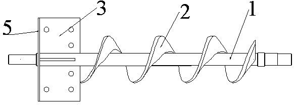
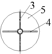
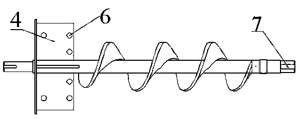
[0024] Such as figure 1 , figure 2 as well as image 3 As shown, an auger convenient for welding includes a auger shaft 1, a auger blade 2 welded on the auger shaft 1, and also includes a first mounting plate 3, a second mounting plate 4, the first The mounting plate 3 and the second mounting plate 4 are fixed at one end of the auger shaft 1, and are arranged in a cross around the auger shaft 1; the first mounting plate 3 and the second mounting plate 4 are both evenly arranged with N mounting holes 6, N=6, three are distributed on the top and bottom of the auger shaft 1; the end of the first mounting plate 3 and the second mounting plate 4 away from the auger blade 2 is also fixed with a retaining ring 5, and the axis of the retaining ring 5 and The axis of the auger shaft 1 coincides; the length of the first mounting plate 3 is equal to the diameter of the retaining ring 5, the length of the second mounting plate 4 is smaller than the diameter of the retaining ring 5; the wi...

Embodiment 2

[0028] The difference is that the first mounting board 3 and the second mounting board 4 are evenly arranged with 4 mounting holes 6, which reduces the number of punching holes and reduces the cost.

Embodiment 3

[0030] The difference is that the first mounting plate 3 and the second mounting plate 4 are evenly arranged with 8 mounting holes 6, which can ensure the auger shaft to be more stable and strengthen the welding quality of the auger shaft and the blade.


PUM


Abstract

The invention discloses an auger convenient in seaming and belongs to the field of augers for agricultural machinery, food machinery and building machinery. The auger comprises a first mounting plate and a second mounting plate which are fixed at one end of an auger shaft and arranged around the auger shaft in a crossed manner. Each of the first mounting plate and the second mounting plate is evenly provided with N mounting holes. A retaining ring is disposed at one end, away from the blades of the auger, of each of the first mounting plate and the second mounting plate. The axis of each retaining ring coincides with the axis of the auger shaft. The length of the first mounting plate equals to the diameter of corresponding retaining ring. The length of the second mounting plate is smaller than the diameter of the corresponding retaining ring. The width of the first mounting plate is larger than that of the second mounting plate. The auger has the advantages horizontal arrangement of the auger shaft is guaranteed by the crossed mounting plates, the mounting plates are designed according to welding clamps, the stability of the auger shaft is enhanced, and the welding quality of auger blades are increased.

Description

technical field [0001] The invention relates to an auger device used in agricultural machinery, food machinery or construction machinery, in particular to an auger which is convenient for welding. Background technique [0002] On the existing spiral auger, there are three main designs of the auger blade: one is to use the integral auger blade to form the casting, in order to facilitate the mold drawing and avoid casting defects, the material thickness of the inner edge line of the auger blade must be used The design scheme of the material thickness greater than the outer edge line part, when the auger device is working, the material wear amount of the outer edge line part is much larger than that of the inner edge line part, so that the material thickness of the outer edge line part is thinner, resulting in the spiral auger The device fails prematurely. The second is that the auger blade is formed by integral drawing and coiling of steel strip material. During the drawing an...

Claims


Application Information

Patent Timeline
IPC IPC(8): B65G33/26
Inventor 罗琳
Owner 安徽顺利生物有限公司
Why Eureka
Try Eureka