A new type of welding auger

A welding auger and a new type of technology, applied in the field of new welding auger, can solve the problems of no positioning parts to ensure the stability of the auger blade, no protection measures for the auger shaft, short service life, etc. Strengthen the strength, bear the force evenly, and ensure the effect of smooth work

Active Publication Date: 2017-02-08
安徽顺利生物有限公司
View PDF6 Cites 0 Cited by
  • Summary
  • Abstract
  • Description
  • Claims
  • Application Information

AI Technical Summary

Problems solved by technology

This utility model is to directly weld the auger blades on the auger shaft. The auger shaft is not equipped with protection measures, and its service life is short, and there is no positioning part to ensure the stability of the auger blades during welding, which is easy to cause Welding is not reliable, there are many welding defects

Method used


Image

  • A new type of welding auger
  • A new type of welding auger

Examples


Embodiment 1

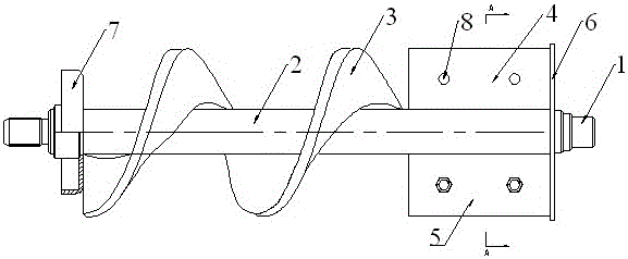
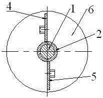
[0024] Such as figure 1 , figure 2 As shown, a new type of welded auger includes an auger shaft 1, an auger blade 3, a shaft sleeve 2, a first positioning plate 4, and a second positioning plate 5, and the auger blade 3 is welded outside the sleeve 2 On the surface, the shaft sleeve 2 is set on the auger shaft 1; the first positioning plate 4 and the second positioning plate 5 are fixed on one end of the auger shaft 1, and the other end is provided with a dust cover 7; the first positioning plate 4, the second positioning plate The plate 5 is vertically fixed on the surface of the shaft sleeve 2, distributed symmetrically around the axis of the auger shaft 1, and the two ends of the two positioning plates are aligned; A retaining ring 6 is fixed, and the axis of the retaining ring 6 coincides with the axis of the auger shaft 1; two mounting holes 8 are provided on the first positioning plate 4 and the second positioning plate 5 .

[0025] In addition, the auger shaft 1 and...

Embodiment 2

[0028] Same as embodiment 1, the difference is that the first positioning plate 4 and the second positioning plate 5 are evenly arranged with four installation holes 8, which can ensure the stability of the auger shaft and enhance the welding quality of the auger shaft and the blades.


PUM


Abstract

The invention discloses a novel welding-on auger and relates to an auger device used for agricultural machines, food machines or building machines. The novel welding-on auger comprises a shaft sleeve, a first locating plate and a second locating plate. An auger blade is welded to the outer surface of the shaft sleeve; the shaft sleeve is sheathed onto an auger shaft; one end of the auger shaft is fixedly provided with the first locating plate and the second locating plate; the other end of the auger shaft is provided with a dust cover; the two locating plates are vertically and fixedly arranged on the surface of the shaft sleeve, and symmetrically distributed around the axis of the auger shaft, and the two locating plates are aligned in both ends; one ends of the two locating plates, far away from the auger blade, are also fixedly provided with a check ring; the axis of the check ring is coincident with the axis of the auger shaft; 2-4 mounting holes are formed in each locating plate. According to the novel welding-on auger disclosed by the invention, the auger blade is welded to the shaft sleeve outside the auger shaft, and thus, the auger shaft can be effectively protected, and moreover, the shaft sleeve is also provided with the locating plates, and thus, the auger blade can be accurately located when welding is performed, and therefore, the welding quality of the auger blade is improved.

Description

technical field [0001] The invention relates to an auger device used in agricultural machinery, food machinery or construction machinery, in particular to a novel welded auger. Background technique [0002] The auger blades of the existing auger equipment have been formed by unit blades and then combined and welded to form a whole auger blade, and the material thickness of the outer edge line of the auger blade is greater than the material thickness of the inner edge line of the auger blade. The wear resistance of the auger blade prolongs its service life, and is beneficial to improve the transmission efficiency of the auger blade, and further improve the working performance of the auger blade. However, the use of welding is faced with certain welding difficulties. The existing auger blades are directly welded on the auger shaft. Stable welding leads to unreliable welding, which will cause welding defects such as cracks and misalignment, which will affect the normal use of ...

Claims


Application Information

Patent Timeline
Patent Type & Authority Patents(China)
IPC IPC(8): B65G33/26
Inventor 董娜黄晓红刘世宇黄添王伟民
Owner 安徽顺利生物有限公司
Why Eureka
Try Eureka