Projection device and optical path difference compensation method for projection device

A technology of projection device and optical path difference, applied in projection device, optics, instrument, etc., can solve the problem of low effect of cooling treatment method

Inactive Publication Date: 2016-04-06
QISDA OPTRONICS (SUZHOU) CO LTD
View PDF9 Cites 0 Cited by
  • Summary
  • Abstract
  • Description
  • Claims
  • Application Information

AI Technical Summary

Problems solved by technology

At present, the commonly used solution is to lower the temperature of the housing 200 to reduce the impact of thermal drift, but the temperature of the housing 200 itself is very high, so the effect of cooling treatment is very low

Method used


Image

  • Projection device and optical path difference compensation method for projection device
  • Projection device and optical path difference compensation method for projection device
  • Projection device and optical path difference compensation method for projection device

Examples


Embodiment Construction

[0027] In order to have a further understanding of the purpose, structure, features, and functions of the present invention, the following detailed descriptions are provided in conjunction with the embodiments.

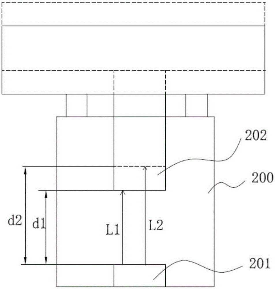
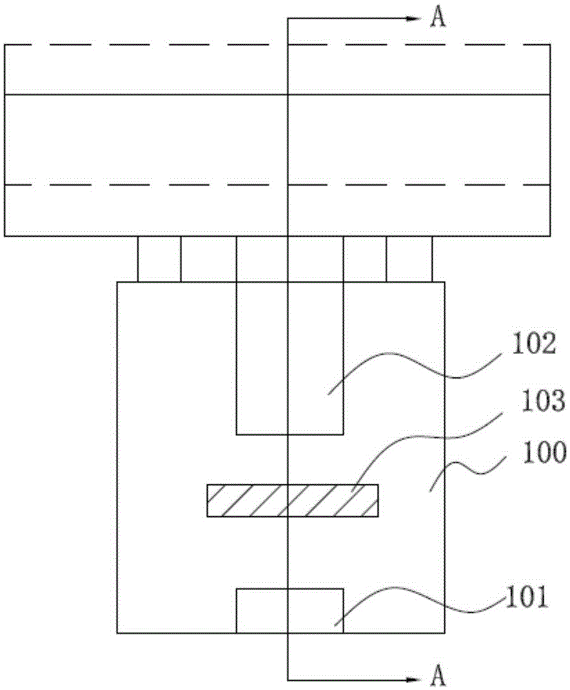
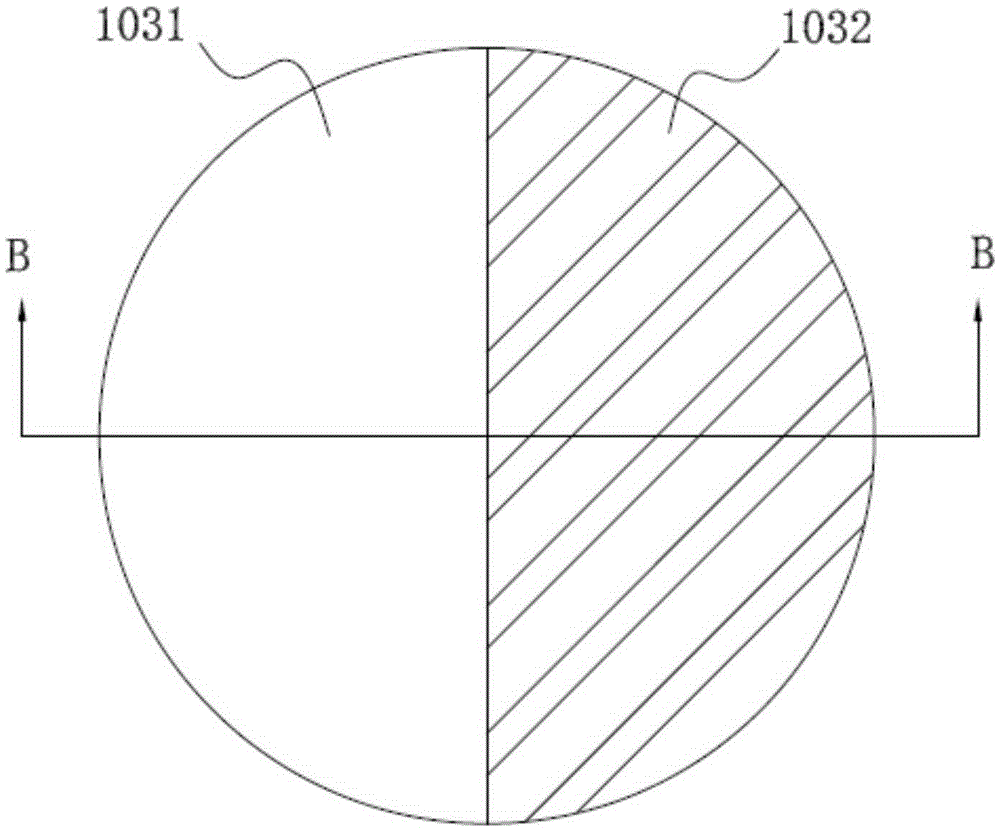
[0028] Such as figure 2 Shown is a schematic structural diagram of the projection device of the present invention. The projection device of the present invention comprises a digital micromirror element 101, a lens 102 and an optical path compensation element 103, the projection apparatus has a light beam passing through the digital micromirror element 101; the lens 102 is arranged on the propagation path of the light beam; the optical path compensation element 103 is disposed between the lens 102 and the digital micromirror element 101, and the optical path compensation element 103 is located on the propagation path of the light beam; wherein, the optical path compensation element 103 has a plurality of areas, such as image 3 as shown, image 3 It is a schematic s...


PUM


Abstract

The invention provides a projection apparatus and a projection apparatus light path difference compensation method. The projection apparatus comprises a digital micromirror element, a lens and a light path compensation element. The projection apparatus is provided with a light beam passing through the digital micromirror element; the lens is arranged on the propagation path of the light beam; the light path compensation element is arranged between the lens and the digital micromirror element and is disposed on the propagation path of the light beam; the light path compensation element is provided with a plurality of areas; the light beam generates different light paths when passing through each area of the plurality of areas, and when the lens generates displacement, one area, which matches the displacement of the lens, in the plurality of areas enters the propagation path so as to compensate the light path difference generated by the displacement of the lens. According to the invention, the light path compensation element is arranged between the digital micromirror element and the lens so that the purpose of compensating the light path difference, which is generated by the displacement of the lens, of the projection apparatus, can be realized.

Description

technical field [0001] The invention relates to a projection device and a method for compensating the optical path difference of the projection device, in particular to a projection device with an optical path compensation element and a method for compensating the optical path difference of the projection device. Background technique [0002] At present, projection devices are widely used in daily life, and general projection devices generate heat during use, such as figure 1 As shown in FIG. 2 , it is a structural schematic diagram of a traditional technology projection device. figure 1 Among them, the projection device includes a housing 200, a digital micromirror device 201 (DMD, Digital Micromirror Device) and a lens 202. In the initial state, the distance between the digital micromirror device 201 and the lens 202 is d1. The optical path that the emitted light beam reaches the lens 202 is L1 (L1=d1*n, n is the refractive index of air); as the working time of the projec...

Claims


Application Information

Patent Timeline
Patent Type & Authority Patents(China)
IPC IPC(8): G03B21/14G03B21/00
Inventor 李礼操
Owner QISDA OPTRONICS (SUZHOU) CO LTD
Why Eureka
Try Eureka