
Non-uniform temperature compensation structure and method of arrayed waveguide grating

An arrayed waveguide grating and arrayed waveguide technology, which is applied in the field of optical communication, can solve the problem of high power consumption of a temperature control unit, and achieve the effect of low power consumption

Active Publication Date: 2020-09-01
SHANGHAI SILIGHT TECH
View PDF13 Cites 0 Cited by
  • Summary
  • Abstract
  • Description
  • Claims
  • Application Information

AI Technical Summary

Problems solved by technology

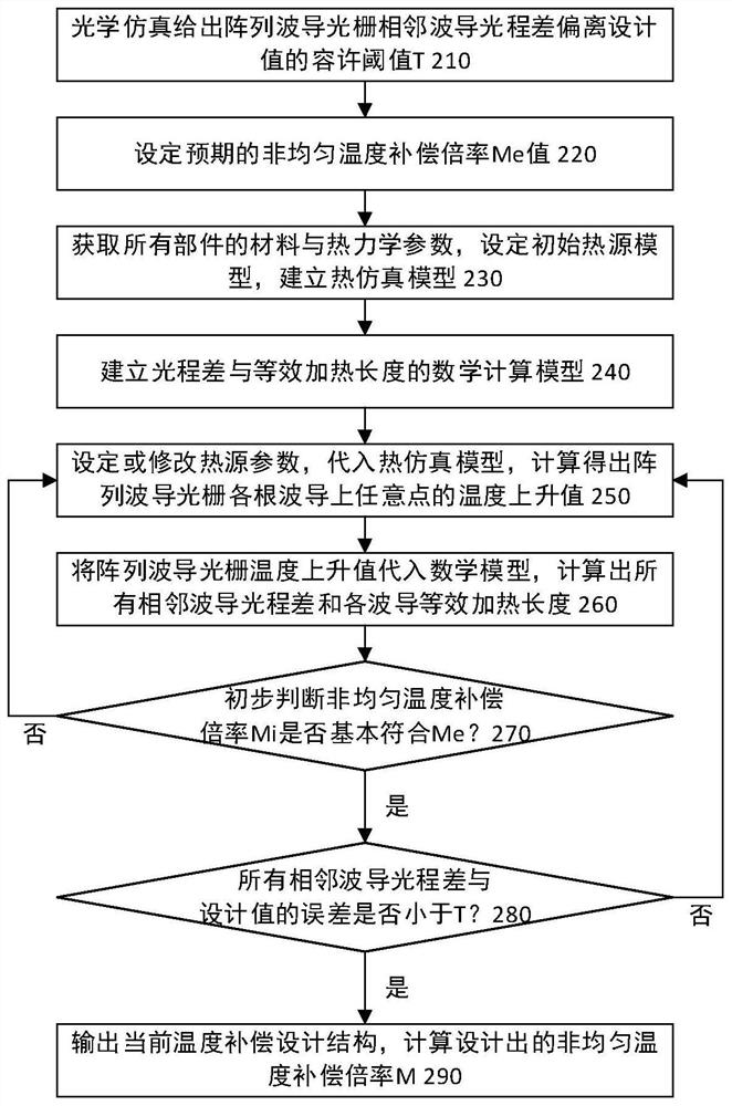
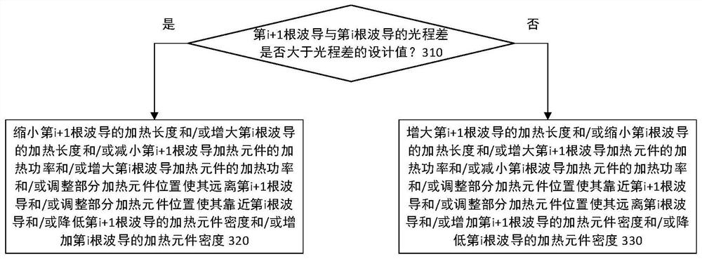
In the prior art, the heating method for temperature control is uniform heating, that is, the entire device of the arrayed waveguide grating is fully heated. Although the purpose of optical path difference compensation can be achieved, the power consumption of the temperature control unit is relatively large

Method used


Image

  • Non-uniform temperature compensation structure and method of arrayed waveguide grating
  • Non-uniform temperature compensation structure and method of arrayed waveguide grating
  • Non-uniform temperature compensation structure and method of arrayed waveguide grating

Examples


Embodiment Construction

[0033] In the following description, the present invention is described with reference to various examples. One skilled in the art will recognize, however, that the various embodiments may be practiced without one or more of the specific details, or with other alternative and / or additional methods, materials, or components. In other instances, well-known structures, materials, or operations are not shown or described in detail so as not to obscure aspects of the various embodiments of the invention. Similarly, for purposes of explanation, specific quantities, materials and configurations are set forth in order to provide a thorough understanding of embodiments of the invention. However, the invention may be practiced without these specific details. Furthermore, it should be understood that the various embodiments shown in the drawings are illustrative representations and are not necessarily drawn to scale.

[0034] In this specification, reference to "one embodiment" or "the...


PUM


Abstract

The invention discloses an arrayed-waveguide grating structure with a function of non-uniform temperature compensation. The arrayed-waveguide grating structure comprises arrayed waveguides and a heating area, wherein the heating area is adjacent to partial regions of the arrayed waveguides and heats the partial regions, and the equivalent heating length of each of the arrayed waveguides is increased along with increasing of the waveguide length. Through the structure, optical path difference changes caused by environment temperature changes can be compensated, and compared with a uniform temperature compensation method, less power required by the non-uniform temperature compensation method is consumed.

Description

technical field [0001] The invention relates to the technical field of optical communication, in particular to a non-uniform temperature compensation structure and method of an arrayed waveguide grating. Background technique [0002] Arrayed waveguide grating is a wavelength division multiplexing / demultiplexing technology. The arrayed waveguide area of ​​arrayed waveguide grating is composed of a series of waveguides with the same length difference. If the length difference between adjacent waveguides is △L, the distance between adjacent waveguides The optical path difference is n△L, where n is the effective refractive index of the waveguide. The relationship between the lengths of adjacent waveguides is described as: if the length of the first waveguide is L 0 , then the length of the second waveguide adjacent to the first waveguide is L 0 +△L, the length of the third waveguide adjacent to the second waveguide is L 0 +2△L,..., and so on, the length of the kth waveguide i...

Claims


Application Information

Patent Timeline
Patent Type & Authority Patents(China)
IPC IPC(8): G02B6/12G02B27/00
CPCG02B6/12009G02B6/12026G02B27/0012
Inventor 李冰严亭
Owner SHANGHAI SILIGHT TECH
Learn More