
Projector

A projector and prism technology, applied in the field of projectors, can solve the problems of decreased light utilization rate, optical path difference, affecting imaging quality, etc., and achieve the effect of good light utilization rate and imaging quality

Active Publication Date: 2018-04-17
QISDA OPTRONICS (SUZHOU) CO LTD +1
View PDF8 Cites 0 Cited by
  • Summary
  • Abstract
  • Description
  • Claims
  • Application Information

AI Technical Summary

Problems solved by technology

Among them, during the transmission process of light, the light passing through the center of the optical element is called the main ray, and the part of the light other than the main ray is called the side light. In the traditional projector, there is an optical path between the main ray and the side ray during the propagation process. Poor, resulting in a decrease in light utilization, which in turn affects the quality of imaging

Method used


Image

  • Projector
  • Projector
  • Projector

Examples


Embodiment Construction

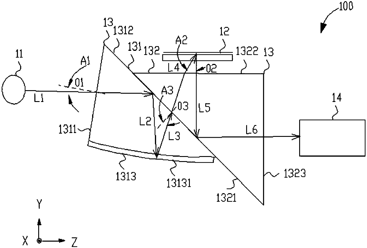
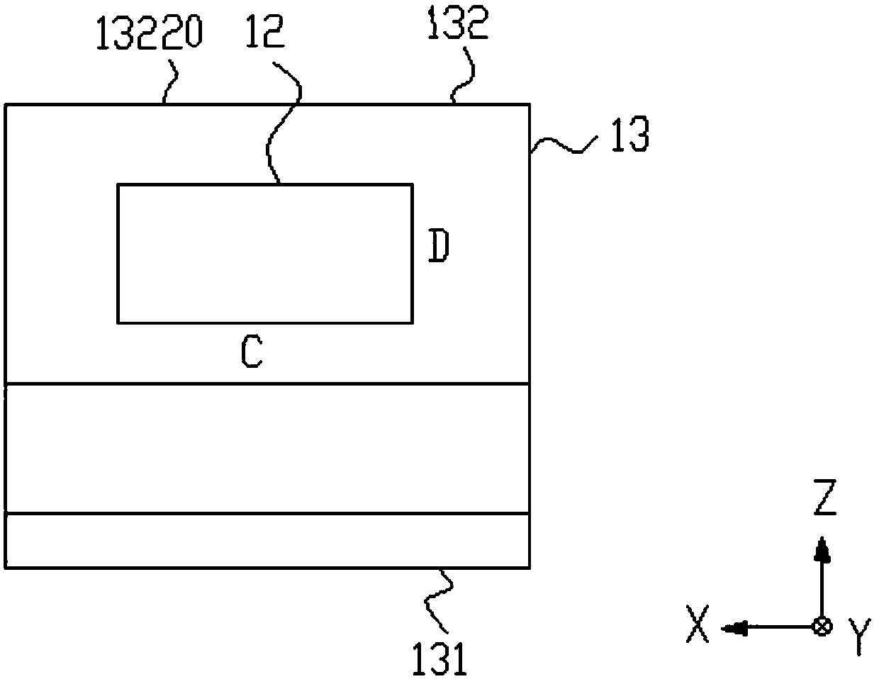
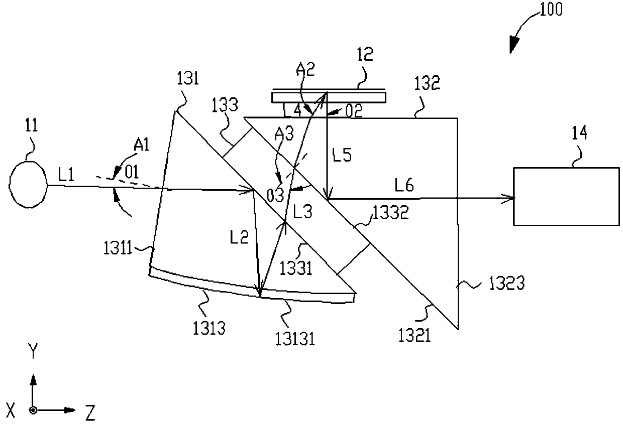
[0028] In order to have a further understanding of the purpose, structure, features, and functions of the present invention, the following detailed descriptions are provided in conjunction with the embodiments.

[0029] figure 1 It is a component structure diagram of the projector according to the first embodiment of the present invention. The projector 100 of the present invention includes a light source 11 , a digital micro-mirror device (Digital Micro-mirror Device, DMD) 12 , a prism group 13 and a lens 14 . Such as figure 2 As shown, the digital micromirror device 12 is a rectangular planar device with a plurality of micromirrors for reflecting incident light into imaging light, and the digital micromirror device 12 has a long side C and a short side D perpendicular to each other. In addition, for the convenience of description, a space with X-axis, Y-axis and Z-axis perpendicular to each other is defined in particular. DMD 12 corresponds to the plane formed by X-axis a...


PUM


Abstract

The invention provides a projector comprising a light source, a digital micro-mirror device, and a prism group. The prism group comprises a first prism and a second prism. The first prism is used to receive and transmit the incident light emitted by the light source, and the second prism is used to receive the incident light transmitted by the first prism, and is used to transmit the above mentioned incident light to the digital micro-mirror device. According to the design conception, the incident light emitted by the light source can be transmitted into the first prism through the first surface of the first prism along the first optical path, and a first included angle A1 is arranged between the normal of the first optical path and the normal of the first surface to compensate the light path difference between the chief ray and the marginal ray of the incident light (A1 is greater than or equal to zero degree, and is less than or equal to thirteen degrees), and therefore the projector is provided with the good light utilization rate and the good imaging quality by comparing with the conventional projectors.

Description

technical field [0001] The invention describes a projector, especially a projector with higher light utilization efficiency. Background technique [0002] A projector is a device that can project images or videos onto the screen. It can be connected to a computer, VCD, DVD, BD, game console, DV, etc. through different interfaces to play the corresponding video signal to achieve a large-screen projection display. way to provide viewers with excellent presentation and visual effects. With the continuous development of electronic technology, projectors are widely used in education, business and home. According to the different working principles of projectors, they can be divided into cathode ray tube projectors (CRT), liquid crystal projectors (LCD) and digital optical processor projectors (DLP). Among them, the imaging principle of the digital optical processor projector projector is: the light emitted by the light source is transmitted to the digital micro-mirror device (D...

Claims


Application Information

Patent Timeline
Patent Type & Authority Patents(China)
IPC IPC(8): G03B21/14G02B17/08G02B5/04
CPCG02B5/04G02B17/0856G03B21/14
Inventor 简志雄
Owner QISDA OPTRONICS (SUZHOU) CO LTD
Learn More