A reflective off-axis digital holographic microscopic measurement device

A digital holographic microscope and measuring device technology, which is applied in the direction of measuring devices, optical devices, instruments, etc., can solve the problems of laser speckle noise aggravation, use of complex optical devices, and reduced visibility, so as to improve visibility and overcome structural complexity , Improve the effect of imaging range

Inactive Publication Date: 2019-03-05
HUAZHONG UNIV OF SCI & TECH
View PDF3 Cites 0 Cited by
  • Summary
  • Abstract
  • Description
  • Claims
  • Application Information

AI Technical Summary

Problems solved by technology

(2) Professor Etienne Cuche, Professor Myung K.Kim from the University of South Florida in the United States and others used a modified device similar to the optical path of the Mach-Zehnder interferometer, which ignored the fact that the optical path of the object light is more than the light path of the reference light. The optical path difference, and the laser with longer coherence length is used to make up for the reduction of the visibility of interference fringes in the hologram, but the laser with better coherence also causes the problem of laser speckle noise aggravation in the hologram (Cuche E, Marquet P, Depeursinge C. Simultaneous amplitude-contrast and quantitative phase-contrast microscopy by numerical reconstruction of Fresnel off-axis holograms[J].Applied optics,1999,38(34):6994-7001 and Kim M K, Yu L, Mann C J. Interference techniques in digitalholography[J].Journal of Optics A:Pure and Applied Optics,2006,8(7):S518.)
(3) In addition to the above two other devices, complex and expensive optical devices also need to be used, which leads to the problems of complex structure and expensive equipment

Method used


Image

  • A reflective off-axis digital holographic microscopic measurement device
  • A reflective off-axis digital holographic microscopic measurement device
  • A reflective off-axis digital holographic microscopic measurement device

Examples


Embodiment Construction

[0031]In order to make the object, technical solution and advantages of the present invention clearer, the present invention will be further described in detail below in conjunction with the accompanying drawings and embodiments. It should be understood that the specific embodiments described here are only used to explain the present invention, not to limit the present invention. In addition, the technical features involved in the various embodiments of the present invention described below can be combined with each other as long as they do not constitute a conflict with each other.

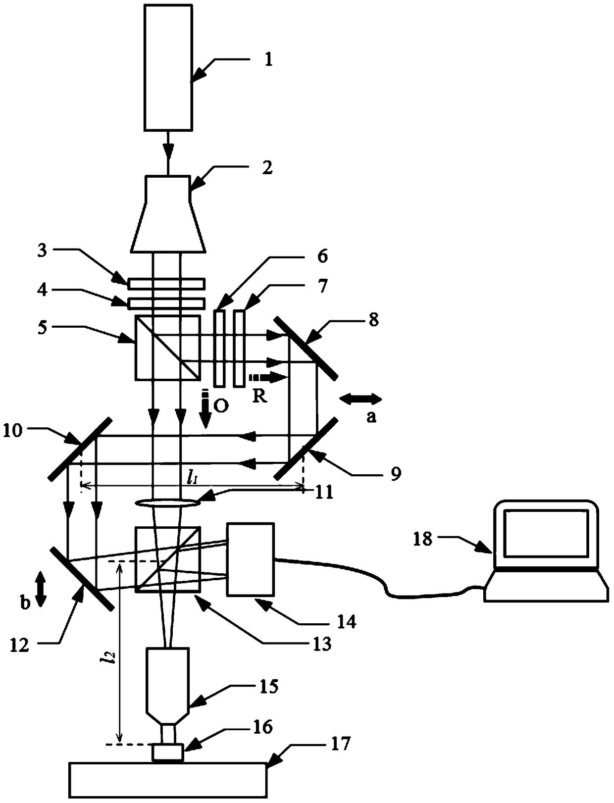
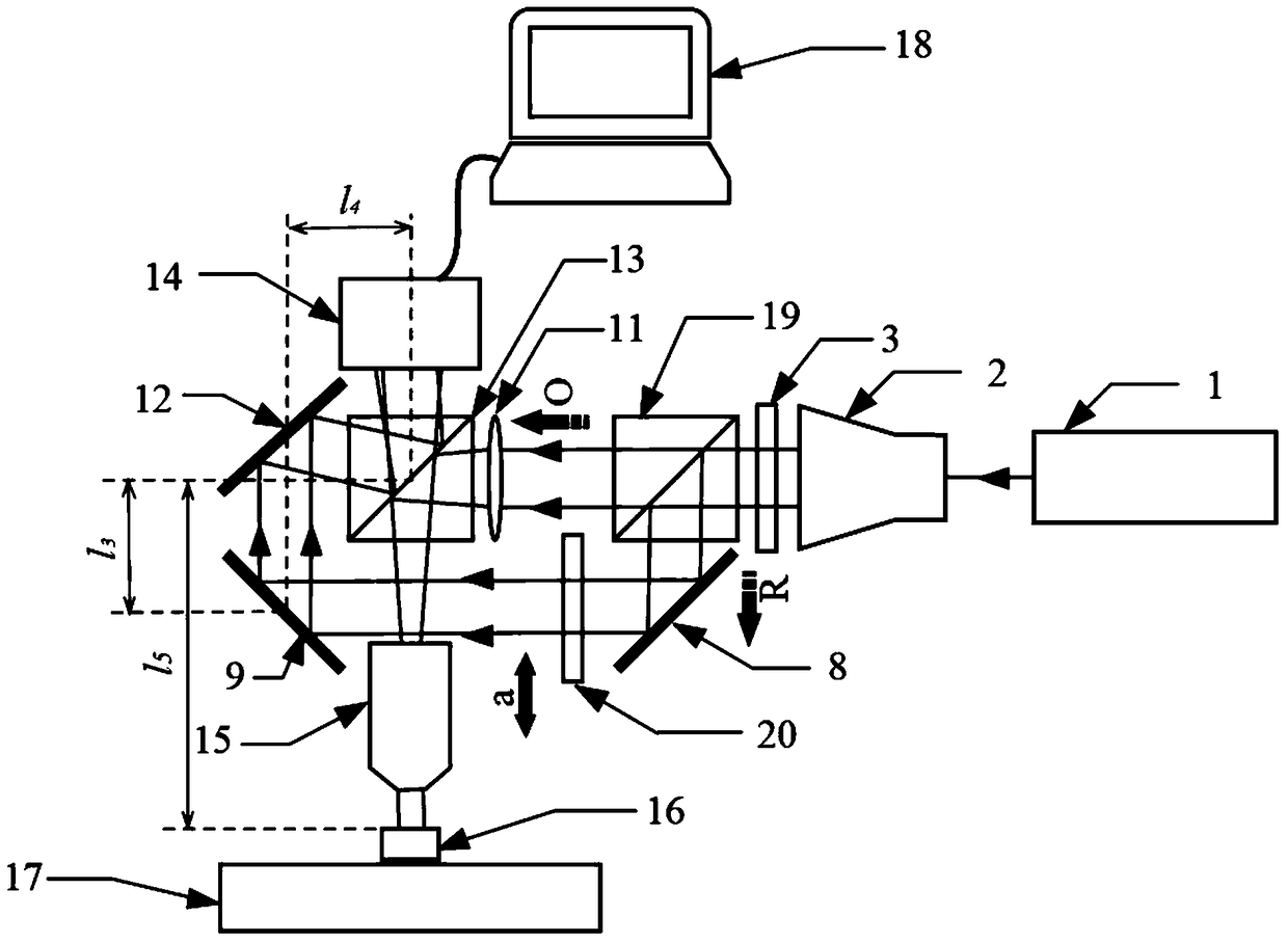
[0032] In the present invention, the beam emitted by the laser is collimated, expanded, and intensity adjusted and then divided into object light O and reference light R by a beam splitter. The object light illuminates the sample evenly, and the reference light is reflected by multiple mirrors Interference occurs at the surface of the image sensor with the object light reflected from the sample s...


PUM


Abstract

The invention discloses a reflection-type off-axis digital holographic microscopy measurement device, which comprises a light source unit, an object light adjusting unit, a reference light adjusting unit and an image processing unit. The reference light adjusting unit comprises an optical path adjustment reflector group and an optical path guidance reflector group. The optical path adjustment reflector group comprises a first reflector and a second reflector, the positions of which are relatively fixed. The first reflector is used for reflecting the reference light R to the second reflector; the second reflector is used for reflecting the input reference light R to the optical path guidance reflector group; the optical path of the reference light R can be adjusted by moving the optical path adjustment reflector group wholly; the optical path guidance reflector group can guide the reference light R, the optical path of which is adjusted, to be input to the image processing unit to have interference with reflected light O'; and the image processing unit is used for processing interference fringes to obtain a sample three-dimensional image. The device can improve the quality of the holographic image.

Description

technical field [0001] The invention belongs to the field of digital holographic microscopic measurement, and more specifically relates to a reflective off-axis digital holographic microscopic device for real-time measurement of three-dimensional topography of non-transparent sample surfaces. Background technique [0002] Since the development of lasers and digital image sensors (CCD or CMOS), digital holography has been widely used. It realizes the reconstruction of three-dimensional shape by performing digital image processing techniques such as fast Fourier transform, spectral filtering, and diffraction light field reconstruction on the recorded hologram. The proposal of off-axis digital holography technology avoids the scanning process of traditional optical shape measurement, and has the advantages of real-time full-field three-dimensional measurement without precise focusing. [0003] At present, when digital holography is used to measure transparent samples, since th...

Claims


Application Information

Patent Timeline
Patent Type & Authority Patents(China)
IPC IPC(8): G03H1/04G01B11/24
Inventor 史铁林洪源廖广兰张贻春王肖陈科鹏文弛王文东王金云
Owner HUAZHONG UNIV OF SCI & TECH
Why Eureka
Try Eureka