
Single board, communication device and single-board power supplying method

A technology of communication equipment and single board, which is applied in the field of communication, can solve the problems of waste of power access board, low power consumption of communication equipment, large volume, etc., and achieve the effect of avoiding waste

Inactive Publication Date: 2014-04-23
HUAWEI TECH CO LTD
View PDF3 Cites 7 Cited by
  • Summary
  • Abstract
  • Description
  • Claims
  • Application Information

AI Technical Summary

Problems solved by technology

Among them, the centralized power supply mode is to supply power to the entire communication equipment through a main power access board (Power Interface Unit, PIU) and a backup power access board, but this power supply mode is only applicable to scenarios with low power consumption of communication equipment. If the power consumption of the communication equipment is large, the design of the power access board is complicated, bulky and costly
With the increase of power consumption of communication equipment, a fixed partition power supply mode has emerged, which divides communication equipment into multiple different partitions. Each partition corresponds to a fixed pair of main power access boards and backup power access boards. Each partition Multiple boards can be plugged in. However, when a new board is inserted, it can only be powered by the main power access board corresponding to the partition where the newly inserted board is located. If the boards plugged into each partition The number is small, and the power consumption of the communication equipment is low at this time, but all the power access boards of each partition are still required to supply power, resulting in a waste of power access boards

Method used


Image

  • Single board, communication device and single-board power supplying method
  • Single board, communication device and single-board power supplying method
  • Single board, communication device and single-board power supplying method

Examples


Embodiment Construction

[0036] The following will clearly and completely describe the technical solutions in the embodiments of the present invention with reference to the accompanying drawings in the embodiments of the present invention. Obviously, the described embodiments are only some, not all, embodiments of the present invention.

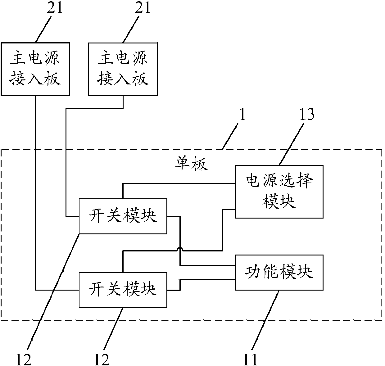
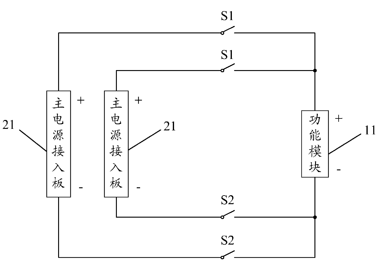
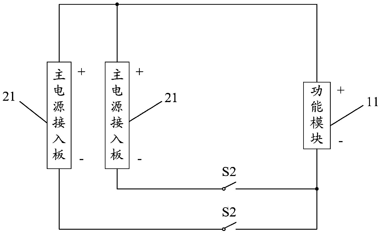
[0037] Such as figure 1 As shown, the embodiment of the present invention provides a veneer 1, including a functional module 11 for realizing the service of the veneer 1. Specifically, the functional modules 11 may be one or more, such as including an optical module, a service chip, etc., the veneer 1 also includes: n switch modules 12, the first ends of the n switch modules 12 are connected to the functional module 11, and the second ends of the n switch modules 12 are used to respectively connect n main power access boards 21, wherein n It is an integer greater than or equal to 2, and the main power access board 21 is connected to the power supply for supplying pow...


PUM


Abstract

The invention discloses a single board, a communication device and a single-board power supplying method and relates to the technical field of communication. When a new single board is inserted, an already used main PIU (power interface unit) is selected preferentially from a plurality of main PIUs for power supplying so as to prevent waste of the main PIUs. The single board includes a function module and also includes n switch modules and a power-supply selection module. First ends of the n switch modules are connected to the function module. Second ends of the n switch modules are used for being connected with the n main PIUs respectively, wherein n is an integer larger than or equal to 2. The power-supply selection module is connected to control ends of the n switch modules and used for detecting the remaining power of the n main PIUs and selecting a main PIU with the smallest remaining power from main PIUs, the remaining power of which is larger than or equal to the rated power of the single board as a power-supplying power interface unit so as to control a switch module connected with the power-supplying power interface unit to be switched on.

Description

technical field [0001] The invention relates to the technical field of communication, in particular to a single board, communication equipment and a single board power supply method. Background technique [0002] Traditional communication equipment is usually powered in two ways, centralized power supply and fixed partition power supply. Among them, the centralized power supply mode is to supply power to the entire communication equipment through a main power access board (Power Interface Unit, PIU) and a backup power access board, but this power supply mode is only applicable to scenarios with low power consumption of communication equipment. If the power consumption of the communication equipment is large, the design of the power access board is complicated, bulky and costly. With the increase of power consumption of communication equipment, a fixed partition power supply mode has emerged, which divides communication equipment into multiple different partitions. Each part...

Claims


Application Information

Patent Timeline
IPC IPC(8): H02J9/00H02J9/06
CPCG06F1/26H02J9/005
Inventor 曹文宗李哲朱品华
Owner HUAWEI TECH CO LTD
Learn More