Method of manufacturing electric resistance welding pipe having excellent characterization of welded seam

A technology of resistance welding and characteristics, applied in the direction of welding of straight welds, manufacturing tools, resistance welding equipment, etc.

Active Publication Date: 2014-04-30
JFE STEEL CORP
View PDF10 Cites 9 Cited by
  • Summary
  • Abstract
  • Description
  • Claims
  • Application Information

AI Technical Summary

Problems solved by technology

As a result, as in Patent Document 1, the strip is hardly work-hardened by the reduction of the lateral edges by the vertical rolls, and even if the amount of upset is reduced in the subsequent fin forming, the strip is fully The finned part is filled, so it is difficult, and the lateral edge of the strip 10 is shaped as described in patent document 2, so the taper disappears completely, and the edge becomes flat

Method used


Image

  • Method of manufacturing electric resistance welding pipe having excellent characterization of welded seam
  • Method of manufacturing electric resistance welding pipe having excellent characterization of welded seam
  • Method of manufacturing electric resistance welding pipe having excellent characterization of welded seam

Examples


Embodiment 1

[0115] Embodiment 1 will be described below.

[0116] Here, an electric resistance welded pipe having a diameter of 600 mm was manufactured using a strip material (steel strip) having a width of 1920 mm and a thickness of 19.1 mm. A test piece was cut from the welded portion of the manufactured electric resistance welded pipe, and the test piece was subjected to a Charpy test to evaluate the performance of the pipe. A Charpy test piece is sampled at each of ten different points along the length of the tube in such a way that the longitudinal direction of the test piece is parallel to the circumferential direction of the tube and the longitudinal center of the notch corresponds to the The center position on the thickness. The test piece was shaped into a JIS52 mm-V-notch impact test piece, impact tested at -46°C, and the Charpy impact value and brittle fracture surface ratio were measured. A Charpy impact value of 125J or more and a brittle fracture surface ratio of 35% or le...

Embodiment 1)

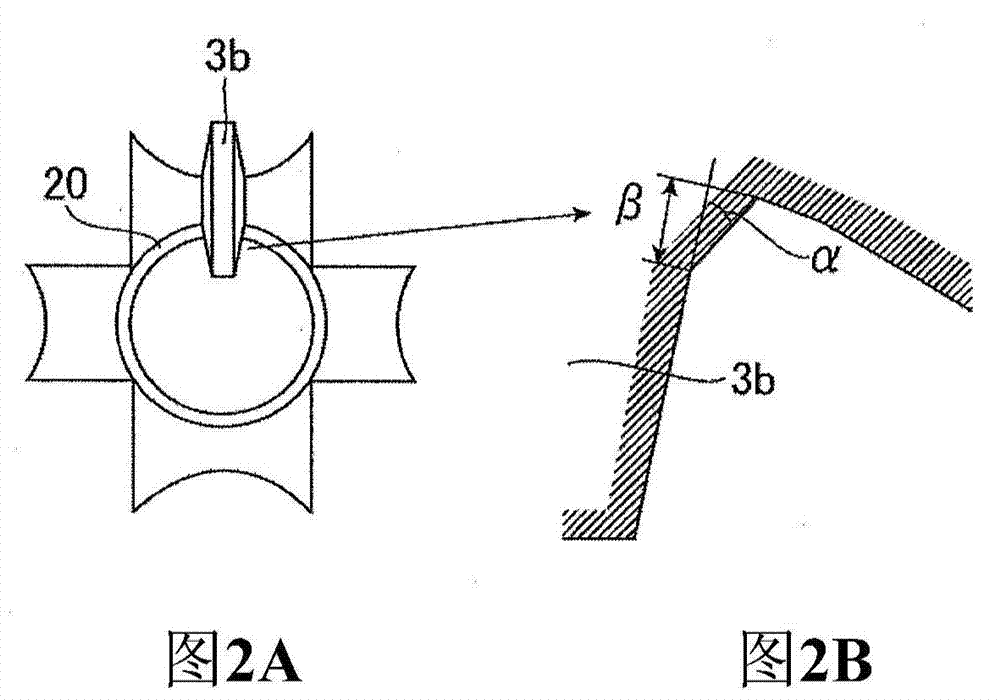
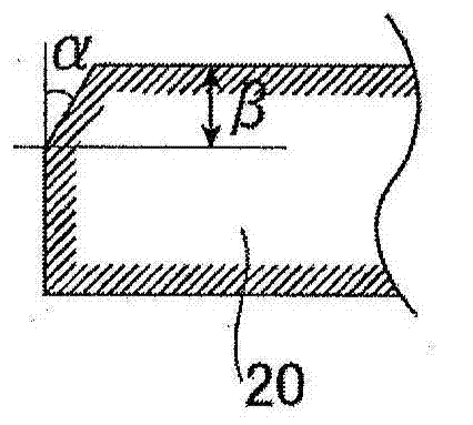
[0118] As Example 1 of the present invention, a resistance welded pipe was manufactured according to the first embodiment. That is, the strip transverse edge at the side that will be the outer surface side of the tube is formed into a tapered shape by a fin-forming end stand whose fins have two angles (the first of the fins The angle is 85° relative to the perpendicular to the axis of the roll). The taper is made to have an angle of inclination α of 30° relative to the vertical edge of the strip.

Embodiment 2)

[0120] As Example 2 of the present invention, a resistance welded pipe was manufactured according to the second embodiment. That is, in the two-stand fin forming, the strip transverse edge at the side to be the tube outer surface side and the strip transverse edge at the side to be the tube inner surface side are respectively formed by the first stand Being tapered, the fins of this first stand have three angles (the second angle of the fins is 40° relative to the perpendicular to the axis of the roll). The inclination angle α at the side to be the tube outer surface side and the inclination angle γ at the side to be the tube inner surface side were made to be 25°.


PUM

PropertyMeasurementUnit
thicknessaaaaaaaaaa
diameteraaaaaaaaaa
widthaaaaaaaaaa

Abstract

A method of manufacturing an electric resistance welding pipe is provided, in which a lateral edge shape is made to be an appropriate shape immediately before electric resistance welding is performed, thereby penetrators are securely removed during the electric resistance welding, consequently an electric resistance welding pipe having excellent characterization of welded seam can be obtained. A fin shape in finpass forming is printed to lateral edges of a strip, thereby the lateral edges of the strip are shaped with predetermined tapering.

Description

[0001] This application is an invention patent with the filing date of November 9, 2006, the application number of 200680040746.9 (the international application number is PCT / JP2006 / 322790), and the title of the invention is "Method for Manufacturing Electric Resistance Welded Pipe with Excellent Welding Seam Characteristics" Divisional application of the application. technical field [0002] The present invention relates to a method of manufacturing a pipe requiring weld toughness such as a linepipe for an oil well or a pipe requiring weld strength such as a casing for an oil well. Background technique [0003] In general, pipes can be broadly classified into welded pipes and seamless pipes. An electric resistance welded pipe, which is a type of welded pipe, is manufactured by bending a sheet into a circle by roll forming or the like, and then butting the edges and welding them. In welded pipe, the weld is generally less tough and strong than the parent strip. In any case...

Claims


Application Information

Patent Timeline
Patent Type & Authority Applications(China)
IPC IPC(8): B21C37/083B21D5/12B23K11/34B23K11/00
CPCB21C37/083B21C37/0822B21C37/0826B23K2201/06B23K11/062B23K33/006B23K2101/06B21C37/08B21D5/12B23K11/00
Inventor 剑持一仁冈部能知横山泰康杉本祐二村上宗义盐谷修松尾信行井上智弘岩崎谦一
Owner JFE STEEL CORP
Why Eureka
Try Eureka