Method for determining positions of wing spars

A wing and spar technology, which is applied in the field of determining the position of the wing spar, can solve problems such as many design problems, high expenditure, and no solution proposed

Inactive Publication Date: 2014-04-30
BEIHANG UNIV
View PDF5 Cites 12 Cited by
  • Summary
  • Abstract
  • Description
  • Claims
  • Application Information

AI Technical Summary

Problems solved by technology

Such a design method will inevitably lead to a long design cycle, high expenditure, many design problems, and ha

Method used


Image

  • Method for determining positions of wing spars
  • Method for determining positions of wing spars
  • Method for determining positions of wing spars

Examples


Embodiment

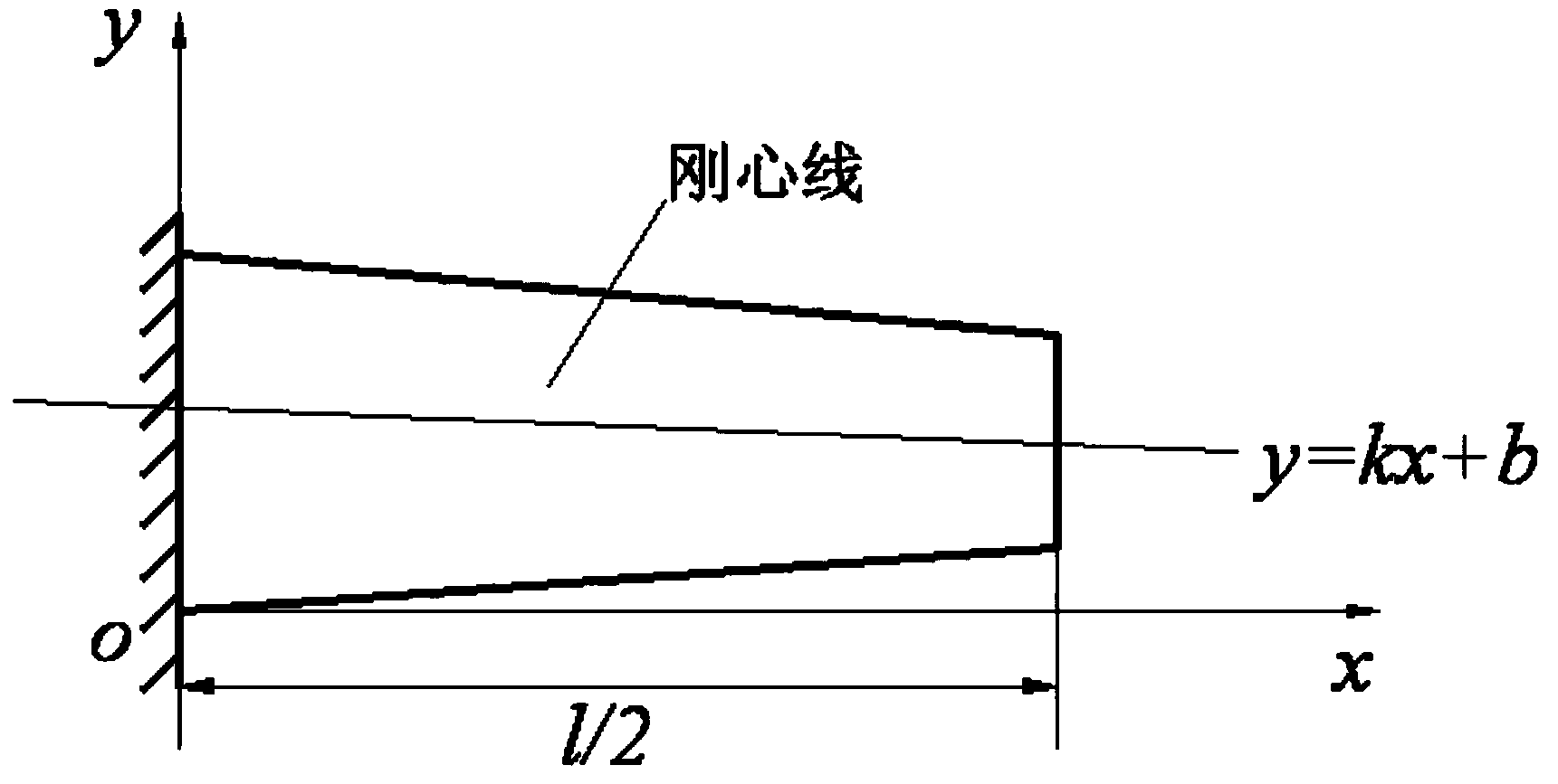
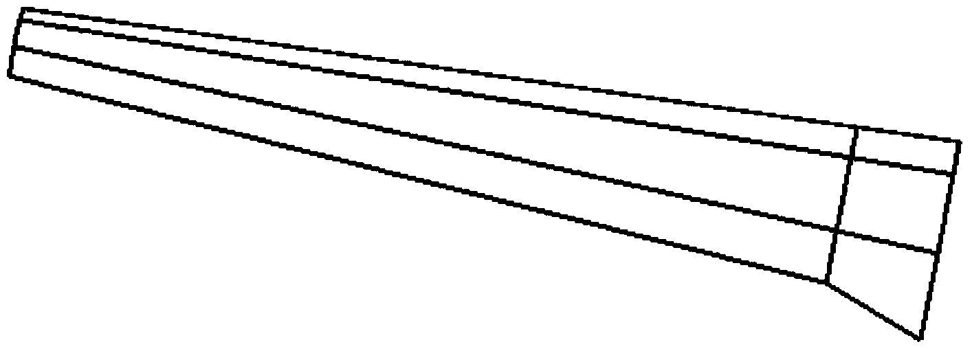
[0108] image 3 is a three-dimensional map of a certain type of UAV wing, Figure 4 For the simplified planar model diagram of the wing, apply the various parameters of the wing to the mathematical optimization model in step 2, divide the wing into 10 sections for consideration, and use the optimization model to optimize the best rigid center position of each section. Fit the 10 rigid center positions with a straight line to obtain the best rigid center line position equation, such as Figure 5 shown.

[0109] According to the airfoil parameters of the embodiment, the wing section is simplified to a simplified diagram consisting of the skin and the front and rear spar webs, such as Image 6 As shown, using the functional relationship between the height and position of the spar and the position of the center of rigidity calculated in step 2, and applying these parameters to the multi-objective optimization model proposed in step 3, the optimal position and optimal position of...


PUM


Abstract

The invention discloses a method for determining the positions of wing spars. The method includes the first step of analyzing and calculating the flying loads of a wing, the second step of designing the flexural and torsional center line position, and the third step of determining the positions of the wing bars. According to the method, the thought that the positions of the wing spars is matched with the flexural and torsional center line and the loads, the flexural and torsional center line position can be rapidly determined according to the characteristic that the wing bears the loads in the initial stage of the design, the determination of the positions of the wing spars can then be completed, the positions of the wing spars of the wing can be matched with the flexural and torsional center line position, the flexural and torsional center line position can be matched with the loads, and therefore the aim of enabling the position of the wing spars, the flexural and torsional center line position and the loads to be matched is achieved; the method provides powerful scientific evidence for the subsequent structural design of the wing; the method for determining the positions of the wing spars is novel, clear in thought, practicable in operation, high in universality and capable of being popularized and applied to the structural design of the double-spar wing with the high span chord ratio.

Description

technical field [0001] The invention belongs to the technical field of aerospace vehicle structure design, and in particular relates to a method for determining the position of a wing spar. Background technique [0002] In the design of aircraft wing structure, the position design of wing spar occupies a very important position. The specific position of the wing spar has a great influence on the stiffness of the structure, which also has an important influence on the force transmission characteristics, vibration characteristics and structural deformation of the wing. If the position of the wing spar is unreasonable, there will be a big difference in the transmission and distribution of the internal force of the wing, and the wing may also have harmful deformation, and even vibration and aeroelasticity problems. [0003] In the previous wing structure design, the structural position and size were first designed according to the design experience, and the analysis and calcula...

Claims


Application Information

Patent Timeline
IPC IPC(8): B64F5/00G06F17/50
Inventor 何景武袁宁宁赵嘉俊刘文章焦守荣
Owner BEIHANG UNIV
Why Eureka
Try Eureka