A semi-electric self-elevating loading and unloading truck

A loading and unloading truck and electric technology, which is applied in the field of storage, stacking and handling equipment, can solve the problems of wasting manpower, low work efficiency, and low efficiency, and achieve the effects of improving work efficiency, reducing work intensity, and improving convenience

Active Publication Date: 2017-06-20
上海海资国际贸易有限公司
View PDF6 Cites 0 Cited by
  • Summary
  • Abstract
  • Description
  • Claims
  • Application Information

AI Technical Summary

Problems solved by technology

There are generally two types of traditional handling equipment. One is that when entering the handling and stacking operations, the goods can only be transported from the ground to the high platform or in the compartment, and the goods will be piled up by manpower later, and the goods will be transported to other places. , another handling equipment is needed for handling operations, which is not efficient, wastes manpower, and costs one more handling equipment; the other is to enter the handling and stacking operations, which can only be carried out by manpower lifting and lowering of goods and climbing onto the carriage platform Operation, such as the pallet forklift called manual self-lifting pallet forklift ZL201010617238.0, although a kind of manual self-lifting pallet forklift that can be lifted into the transport compartment together with the goods is disclosed, it solves the problem of loading and unloading, compartment loading and unloading by one pallet forklift. A series of logistics operations such as placement, site transportation, etc., but relative to cargo lifting, vehicle body lifting, and lowering operations are all done manually, the operation is time-consuming and laborious, and the work efficiency is low

Method used


Image

  • A semi-electric self-elevating loading and unloading truck
  • A semi-electric self-elevating loading and unloading truck
  • A semi-electric self-elevating loading and unloading truck

Examples


Embodiment Construction

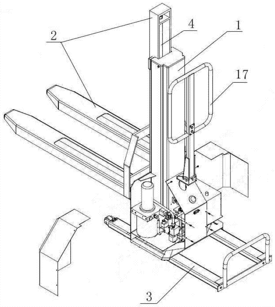
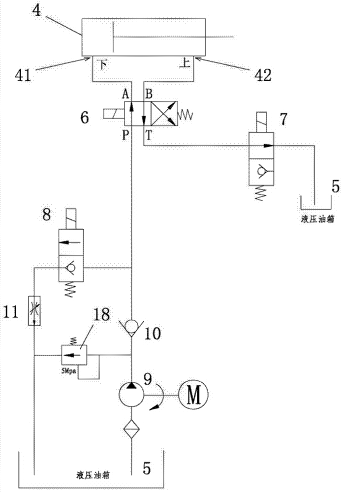
[0034] figure 1 A semi-electric self-elevating loading and unloading truck is shown, including a car body 1, a fork frame 2, a hydraulic system, and a telescopic caster frame 3; the fork frame 2 can be guided and moved up and down on the car body 1, The telescopic caster frame 3 is guided and moved forward and backward and is arranged at the lower end of the vehicle body 1; the hydraulic system includes a double-acting oil cylinder 4 and a hydraulic oil tank 5; the cylinder body of the double-acting oil cylinder 4 is connected with the vehicle The body 1 is fixedly connected, the piston rod of the double-acting oil cylinder 4 is in transmission connection with the fork frame 2, and the double-acting oil cylinder 4 is used to drive the lifting or lowering of the fork frame 2 or the car body 1; The hydraulic system is an electro-hydraulic system, and the hydraulic system is provided with a two-position four-way reversing solenoid valve 6, a first oil drain solenoid valve 7, a se...


PUM


Abstract

The invention discloses a semi-electric self-lifting loading and unloading car which comprises a car body, a cargo fork carrier, a hydraulic system and a telescopic trundle frame. The hydraulic system is an electric hydraulic system which is provided with a two-position-four-way reversing solenoid valve, a first oil drainage solenoid valve, a second oil drainage solenoid valve and an oil pump. Two oil outlets of the two-position-four-way reversing solenoid valve are communicated with an upper oil inlet and a lower oil inlet of a double-effect oil cylinder respectively, an oil inlet of the two-position-four-way reversing solenoid valve is communicated with a hydraulic oil tank through a single-way valve and the oil pump, and an oil discharging opening of the two-position-four-way reversing solenoid valve is communicated with the hydraulic oil tank through the first oil drainage solenoid valve. The oil inlet of the two-position-four-way reversing solenoid valve is communicated with the hydraulic oil tank through another oil drainage branch, and the second oil drainage solenoid valve and a throttle valve are arranged in series. Through ingenious arrangement of the solenoid valve hydraulic system, operation such as loading, unloading, car body climbing and car body descending of the whole loading and unloading car can be controlled electrically, the easy degree and labor-saving degree of the operation and working efficiency are greatly improved, and labor intensity is greatly lowered.

Description

technical field [0001] The invention relates to forklift equipment, in particular to storage stacking and handling equipment. Background technique [0002] Warehousing stacking and handling equipment is a common equipment for many enterprises to carry or stack small goods. Its low cost and easy operation are very popular among enterprises. There are generally two types of traditional handling equipment. One is that when entering the handling and stacking operations, the goods can only be transported from the ground to the high platform or in the compartment, and the goods will be piled up by manpower later, and the goods will be transported to other places. , another handling equipment is needed for handling operations, which is not efficient, wastes manpower, and costs one more handling equipment; the other is to enter the handling and stacking operations, which can only be carried out by manpower lifting and lowering of goods and climbing onto the carriage platform Operat...

Claims


Application Information

Patent Timeline
Patent Type & Authority Patents(China)
IPC IPC(8): B66F9/065B66F9/22B66F9/24
Inventor 倪莉
Owner 上海海资国际贸易有限公司
Why Eureka
Try Eureka