
A medical transport vehicle with a foldable protective cover

A protective cover and transfer vehicle technology, which is applied in the field of medical equipment, can solve problems such as not being able to see the wind, the impact of patient pain, and the patient being exposed to the sun and rain, and achieve the effect of reducing physical requirements and reducing the risk of injury

Active Publication Date: 2022-03-08
BEIJING YOUAN HOSPITAL CAPITAL MEDICAL UNIV
View PDF8 Cites 0 Cited by
  • Summary
  • Abstract
  • Description
  • Claims
  • Application Information

AI Technical Summary

Problems solved by technology

The patient transfer vehicles currently used in clinical practice do not have the function of sheltering from wind and rain. When passing through outdoor roads without corridor bridges, patients are exposed to the outside. In bad weather, patients will inevitably be exposed to the sun and rain during the transfer process. There are also some special patients. Can't see the wind, it is easy to have a very bad impact on the patient's pain during the transfer process, and some life-threatening situations may occur in severe cases

Method used


Image

  • A medical transport vehicle with a foldable protective cover
  • A medical transport vehicle with a foldable protective cover
  • A medical transport vehicle with a foldable protective cover

Examples


Embodiment 1

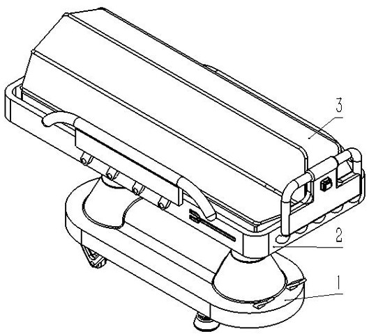
[0110] Such as figure 1 Said, is a kind of medical transfer vehicle with folding protective cover of the present invention.

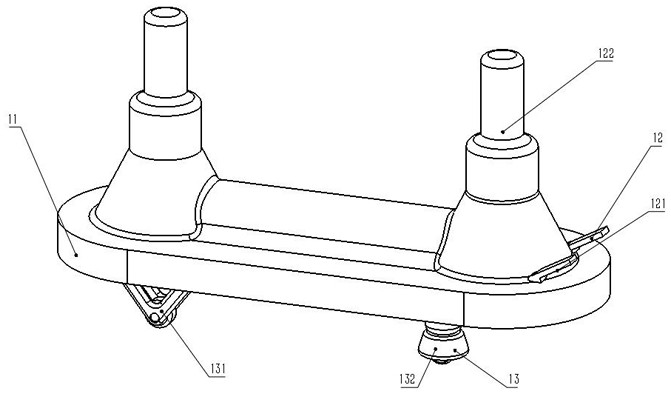
[0111] It includes a bottom assembly 1, a bed body assembly 2 and a protective assembly 3; the bottom assembly 1 includes a chassis 11, a lifting part 12 and a moving part 13; the lifting part 12 is located at the top of the chassis 11; the moving part 13 is located at the bottom of the chassis 11 The bed body assembly 2 includes a bed body 21, a lifting seat 22, an armrest part 23, a push-pull part 27, a nursing part 25 and a bed body power supply assembly 28; 12 are integrally connected; the armrest parts 23 are located on both sides of the bed body 21; The bottom of the body 21; the bed body power supply assembly 28 is connected with the protective assembly 3 through wires, and provides power for the protective assembly 3; the protective assembly 3 includes a shield controller 31, a shield 32, a shield support frame 33, and a shield movement assembly ...

Embodiment 2

[0122] Such as Figure 2-14 As shown, this embodiment adds the following technical features on the basis of Embodiment 1:

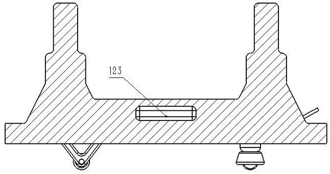
[0123] The lift controller 121 is located on the top of the chassis 11 . The lifting controller 121 is a pedal structure, which controls the movement of the elevator 122 during use to realize smooth lifting. The lifting power supply 123 is arranged inside the chassis 11 to provide power for the lift 122 .

[0124] The directional pulley 131241 is installed on one side of the bottom surface of the bed body 21, and the universal wheel 132 is arranged on the other side of the bottom surface of the bed body 21, and the directional pulley 131241 and the universal wheel 132 are integrally connected with the bed body 21; The use of the wheels 132 at the same time can not only enhance the overall flexibility, but also not be too flexible to be difficult to handle. The bed body 21 is a rectangular plate structure.

[0125] The push-pull part 27 is arranged at ...

Embodiment 3

[0151] Such as Figure 15-16 As shown, this embodiment adds the following technical features on the basis of Embodiment 1:

[0152] The bed body 21 includes a lighting component 26, and the lighting component 26 is connected with a bed body power supply assembly 28 through wires.

[0153] The lighting components 26 are located at both ends of the bed body 21 . The lighting component 26 includes a lighting controller 261 and a lighting lamp 262 . The lighting controller 261 is arranged on one side of the push-pull part 27, and is connected with the bed body power supply assembly 28 and the lighting lamp 262 by wires, and the lighting controller 261 can control the switching of the lighting lamp 262.

[0154] The lighting lamp 262 is arranged on the side of the bed body 21 opposite to the push-pull part 27, controlled by the lighting controller 261, and can illuminate the outdoor environment during use.


PUM


Abstract

The invention discloses a medical transfer vehicle with a foldable protective cover, which includes a bottom assembly, a bed body assembly and a protective assembly; the bottom assembly includes a chassis, a lifting part and a moving part; the lifting part is located on the top of the bottom frame; The parts are located at the bottom of the chassis; the bed body assembly includes the bed body, lifting seat, armrest parts, push-pull parts, nursing parts and bed body power supply assembly; one end of the lifting seat is fixed on the bottom of the bed body, and the other end is integrally connected with the lifting part; the armrest The components are located on both sides of the bed; the push-pull components are located at one end of the bed; the nursing components include installation holes, infusion rods and oxygen cylinder installation positions; the bed power supply components are located at the bottom of the bed; the bed power supply components are connected to the protective components through wires, Provide power for the shielding components; the shielding components include a shield controller, a shield, a shield support frame, and a shield moving component; the shield is located on the top of the bed body; the shield moving component is located at the bottom of the bed body.

Description

technical field [0001] The invention belongs to the technical field of medical devices, and in particular relates to a medical transfer vehicle with a foldable protective cover. Background technique [0002] When transporting disabled or critically ill patients, it is necessary to use a transfer vehicle to transfer the patient to other departments or examination rooms. The patient transfer vehicles currently used in clinical practice do not have the function of sheltering from wind and rain. When passing through outdoor roads without corridor bridges, patients are exposed to the outside. In bad weather, patients will inevitably be exposed to the sun and rain during the transfer process. There are also some special patients. If you can't see the wind, it is easy to have a bad impact on the patient's pain during the transfer process, and some life-threatening situations may occur in severe cases. [0003] Aiming at the above problems, the present invention provides a medical ...

Claims


Application Information

Patent Timeline
Patent Type & Authority Patents(China)
IPC IPC(8): A61G1/02A61G1/04F21V33/00F21W131/20
CPCA61G1/02A61G1/04F21V33/0072F21W2131/20
Inventor 吕婧
Owner BEIJING YOUAN HOSPITAL CAPITAL MEDICAL UNIV
Learn More