
A Grouting Filling System for the Caving Area of ​​a Broken Roof

A technology for breaking roof and caving zone, applied in fillings, safety devices, mining equipment, etc., can solve the problems of high caving zone height, limited injection height and poor effect in thick coal seams, and achieve the effect of slowing surface subsidence and mining. The effect of small filling contradiction and high filling rate

Inactive Publication Date: 2016-01-06
SHANDONG UNIV OF SCI & TECH
View PDF5 Cites 0 Cited by
  • Summary
  • Abstract
  • Description
  • Claims
  • Application Information

AI Technical Summary

Problems solved by technology

[0005] CN102444419A A kind of thin coal seam broken roof tube drag filling system discloses a kind of thin coal seam broken roof trusteeship filling system, although it has realized the thin coal seam mined-out area filling under the broken roof condition, but its system still has some defects, such as , the high-level filling steel pipe described in the system only exists under the premise of gob-side entry retention; under the action of pump pressure, the filling slurry is injected into the void of gangue through the filling pipe arranged on the floor of the goaf, and its injection height is limited, only It is suitable for thin coal seams. For thick and medium-thick coal seams, the height of the caving zone is large, and the filling effect is poor only by pumping the filling pipe arranged on the bottom plate of the working face to the caving gangue gap.

Method used


Image

  • A Grouting Filling System for the Caving Area of ​​a Broken Roof
  • A Grouting Filling System for the Caving Area of ​​a Broken Roof
  • A Grouting Filling System for the Caving Area of ​​a Broken Roof

Examples


Embodiment Construction

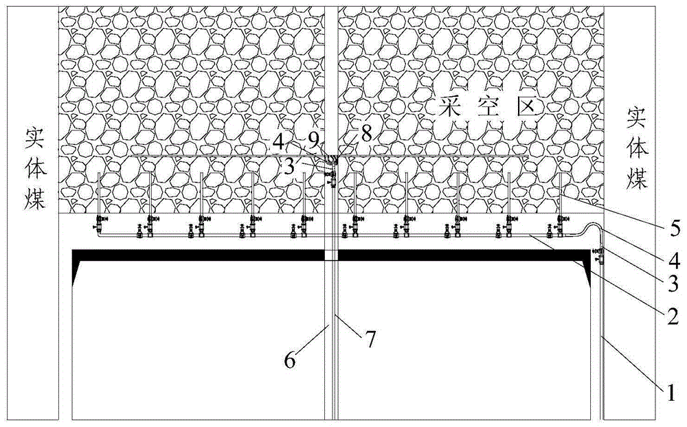
[0028] The present invention discloses a grouting filling system for the caving area of ​​a broken roof. In order to make the advantages and technical solutions of the present invention clearer and clearer, the present invention will be further clearly and completely described below in combination with specific embodiments.

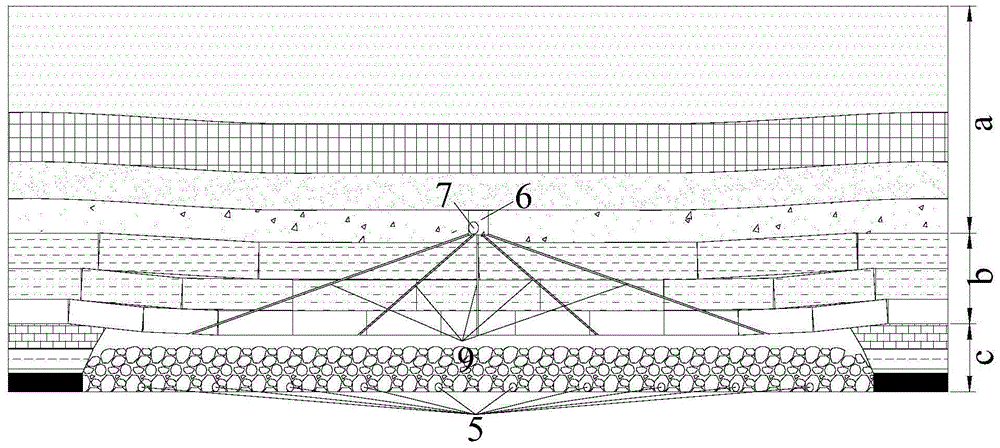
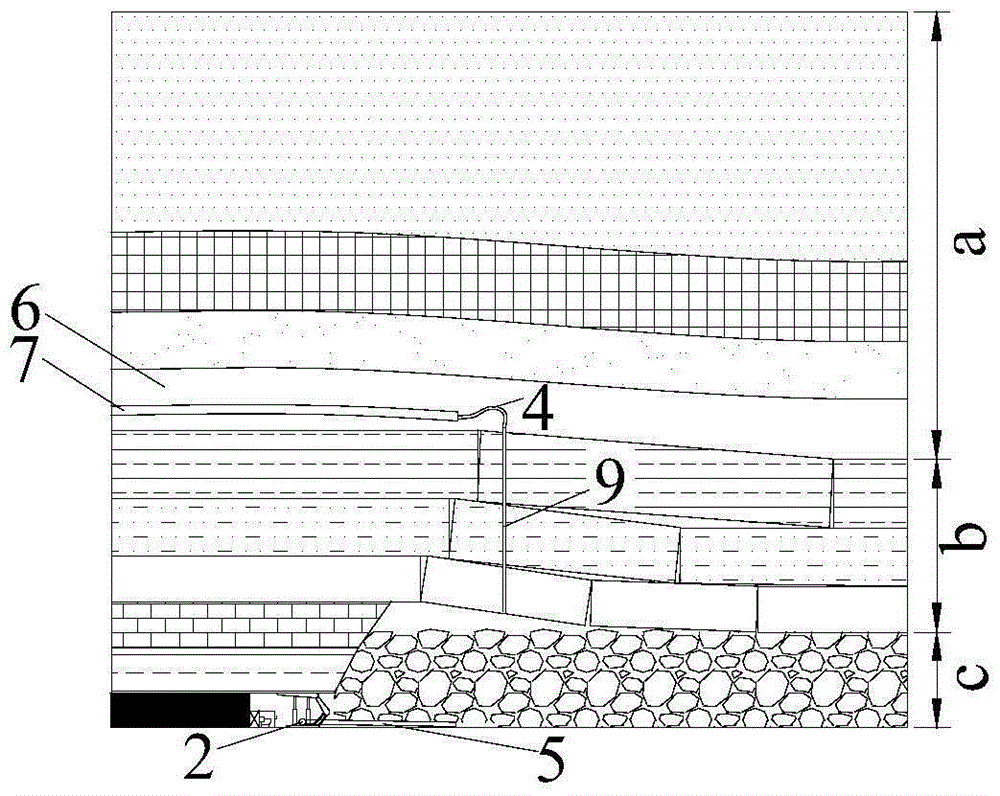
[0029] The curved subsidence zone a is the part of the rock formation that guides the top boundary of the water fracture zone to the surface;

[0030] The fissure zone b refers to the part of the rock stratum that is located above the caving zone and has water-conducting fissures connected to the goaf, but the continuity is not damaged;

[0031] The caving zone c refers to the part of the rock formation that breaks away from the rock matrix, loses continuity, and is in the form of irregular rock blocks or layered rock blocks caving to the goaf.

[0032] to combine Figure 1 to Figure 3 As shown, the present invention is a grouting filling system for the ...


PUM


Abstract

The invention discloses a cracked roof caving region grouting filling system. The cracked roof caving region grouting filling system comprises a grouting filling roadway, a filling roadway filling main pipe, a reducing multi-way body, a casing pipe, anti-wear rubber hoses and grouting drilling holes, wherein the filling roadway filling main pipe is arranged in the filling roadway, the grouting filling roadway is arranged above a working face, the reducing multi-way body is installed on the filling roadway filling main pipe, the anti-wear rubber hoses are connected to the reducing multi-way body through connecting parts, the grouting drilling holes are distributed by a certain angle in a sector-shaped mode, the depth of the grouting drilling holes can reach a caving region, the casing pipe and the grouting drilling holes are glued together through cement grout, and the casing pipe is connected with the anti-wear rubber hoses through the connecting parts. Compared with the prior art, the mode that working face grouting and filling roadway grouting are combined is adopted for the system, and grouting filling of a cracked roof caving region of a thin or medium-thick or thick coal bed can be achieved; working face grouting and filling roadway grouting are adopted for the system, working face production is basically not affected, mining and filling contradiction is small, and the yield of the filling working face is greatly increased.

Description

technical field [0001] The invention relates to a coal mine filling system, in particular to a grouting filling system for a broken roof caving area. Background technique [0002] At present, coal mine filling technologies widely used in my country mainly include paste filling technology, paste-like filling technology, high water filling technology, ultra-high water filling technology, gangue filling technology, etc. The above filling technologies are all under the condition of complete roof For filling, a certain filling time and space must be guaranteed while filling. Although the above-mentioned filling technologies have formed a relatively complete system and process, the above-mentioned various filling methods all fill the goaf under the premise that the roof of the goaf is complete. Difficult, not suitable for goaf filling under broken roof conditions. [0003] In view of the fact that my country's "three undercuts" coal pressure is serious, and the broken roof coal s...

Claims


Application Information

Patent Timeline
Patent Type & Authority Patents(China)
IPC IPC(8): E21F15/08
Inventor 江宁张新国郭惟嘉陈绍杰常西坤张保良张士川陈军涛李杨杨孙熙震王海龙赵金海路畅毕成尚晓龙张涛
Owner SHANDONG UNIV OF SCI & TECH
Learn More