Quick connector for cables

A connector, fast technology, applied in the direction of transmission element or pulley rope or cable, textile cable, belt/chain/gear, etc., can solve the problems of pulling out the cable, wrong connection, complicated disassembly method, etc. The effect of outputting cables and not wasting materials

Active Publication Date: 2014-04-30
宁波迅联机械制造有限公司
View PDF9 Cites 15 Cited by
  • Summary
  • Abstract
  • Description
  • Claims
  • Application Information

AI Technical Summary

Problems solved by technology

However, in the actual use process, there may be wrong connections or the need to pull out the cable, and pulling the cable out of the connector cannot be achieved.
The Chinese utility model patent "Wire Rope Quick Connector" with the announcement number CN203161967U (application number 201320199352.5) ​​discloses a wire rope quick connector with disassembly function, which mainly uses bolts and nuts to realize its disassembly function. The locking effect of this structure is During long-term use, the loosening of bolts and nuts may affect the firmness of the connection, and the disassembly method is more complicated, and the connection and disassembly process takes a long time

Method used


Image

  • Quick connector for cables
  • Quick connector for cables
  • Quick connector for cables

Examples


Embodiment 1

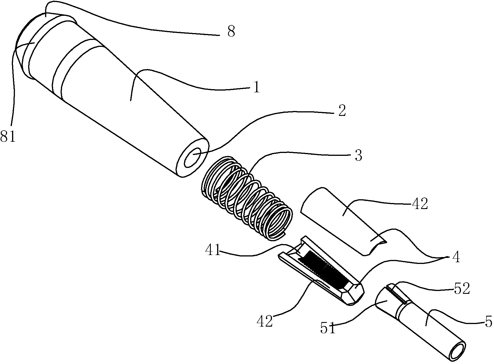
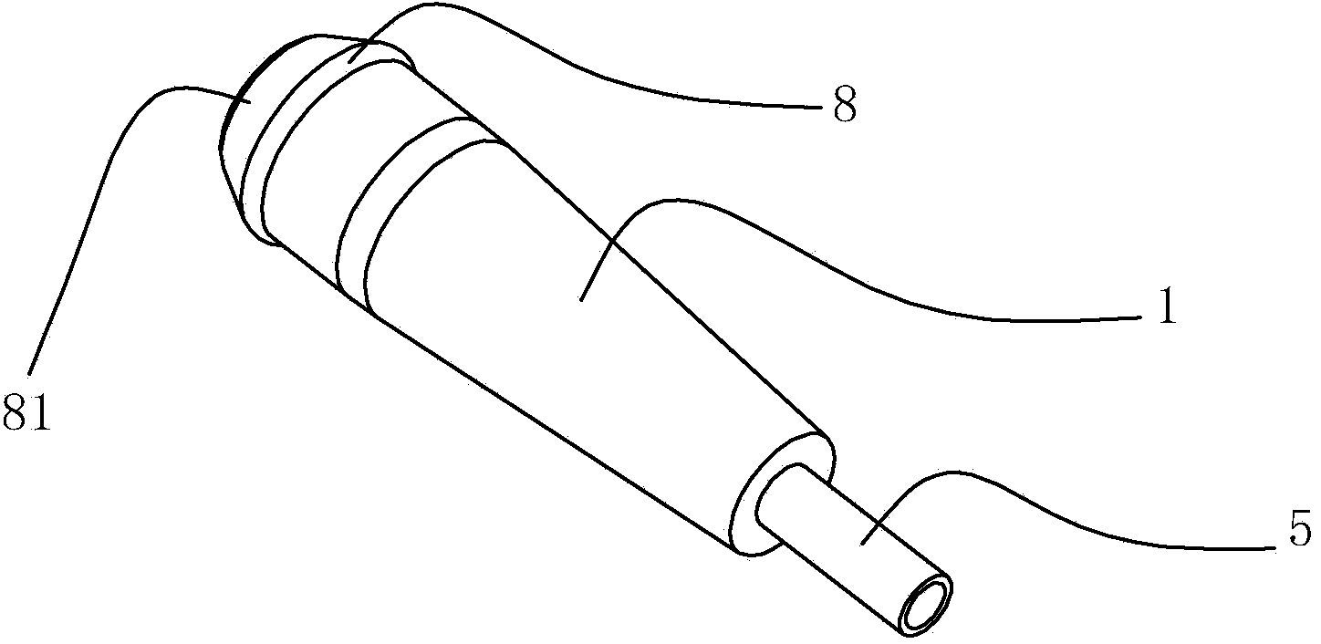
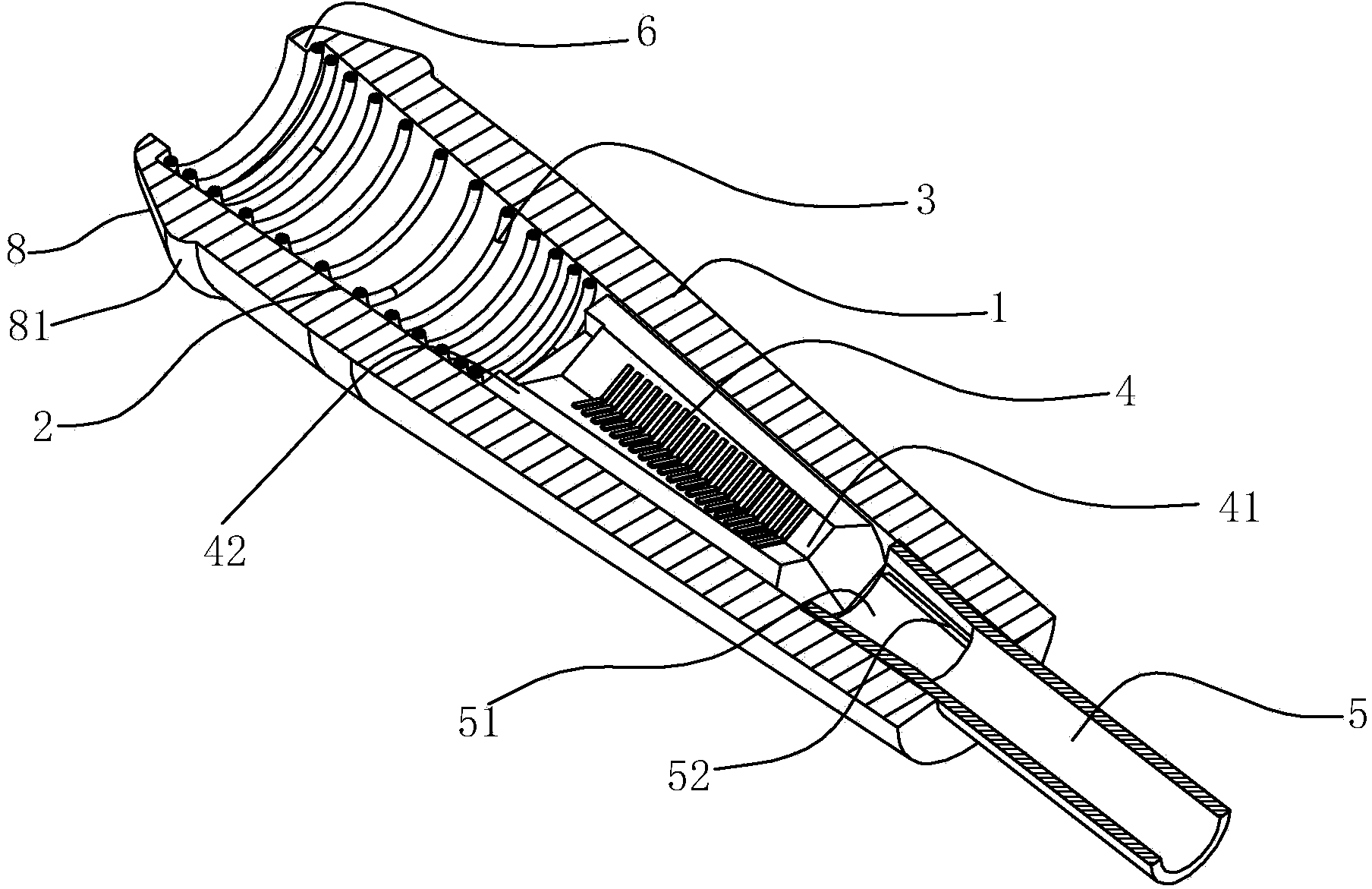
[0022] Such as figure 1 , figure 2 , image 3 and Figure 4 As shown, the quick connector for cables in this embodiment includes a sleeve 1 with a tapered through hole 2, and in the tapered through hole 2, the first A spring 3 and a wire clip 4, the first end of the first spring 3 is against the large diameter end wall of the tapered through hole 2, the second end of the first spring 3 is against the first end of the wire clip 4, the described The clamp 4 includes at least two jaws 42, the inside of the jaws 42 has a groove 41 extending along the axial direction of the tapered through hole 2, the sleeve 1 also includes a push tube 5, the first of the push tube 5 One end is located in the small-diameter end of the tapered through hole 2 and abuts against the second end of the clamp 4 , and the second end of the push tube 5 protrudes out of the tapered through hole 2 .

[0023] In order to achieve reliable and firm connection during the cable connection process, in the dire...

Embodiment 2

[0030] Such as Figure 5 , Image 6 and Figure 7 As shown, the difference from the first embodiment is that the second end of the push tube 5 has an outer flange 53 in order to facilitate the operation when the quick connector is used to release the cable and facilitate the user to press the push tube.

[0031] In order to increase the locking degree of the cable in the quick connector and ensure the elastic force for locking the cable, the outer circumference of the push tube 5 protruding from the tapered through hole 2 is provided with a second spring 9 , One end of the second spring 9 abuts against the circumferential end surface of the small-diameter end of the sleeve 1 , and the other end abuts against the outer flange 53 of the push tube 5 .

[0032] The difference from Embodiment 1 during use is that due to the elastic force generated by the second spring 9 on the sleeve 1, the pulling force of the push tube 5 moving to the small diameter end of the tapered through h...


PUM


Abstract

The invention relates to a quick connector for cables. The quick connector for the cables comprises a sleeve with a conical through hole, wherein a first spring and a cable clamp are arranged in the conical through hole in sequence from the large-diameter end to the small-diameter end, the first end of the first spring abuts against the wall of the large-diameter end of the conical through hole, the second end of the first spring abuts against the first end of the cable clamp, the cable clamp comprises at least two clamping jaws, grooves extending in the axial direction of the conical through hole are formed in the inner sides of the clamping jaws, an ejector sleeve is further arranged in the sleeve, the first end of the ejector sleeve is located at the small-diameter end of the conical through hole and abuts against the second end of the cable clamp, and the second end of the ejector sleeve stretches out of the conical through hole. The quick connector for the cables has the connecting function of a traditional quick connector and has the advantages that the cables can be released conveniently, both time and labor are saved, energy is saved, environmental friendliness is achieved, connecting reliability and connecting stability can be guaranteed due to the adoption of the structure, and the quick connector is convenient to use and practical.

Description

technical field [0001] The invention relates to a fastening device for cables, in particular to a quick connector for cables. Background technique [0002] In production and life, it is often encountered that cable connections are required. A wide variety of connectors have appeared in various fields of production and life, which can be used for connection between cables. In the process of continuous development of technology, there has been a connector structure that can be connected quickly and conveniently, such as the Chinese utility model patent "Steel Wire Connector" with the announcement number CN2663731Y (patent number ZL200320122248) and the announcement number CN1278466C (patent number ZL02157258 .5) The connectors disclosed in the Chinese invention patent "Steel Strand Quick Connector" all include a sleeve (or sleeve), a wire clip, and a first spring, and use a tapered cavity to realize the bite and clamping of the steel wire . However, in the actual use process...

Claims


Application Information

Patent Timeline
Patent Type & Authority Applications(China)
IPC IPC(8): F16G11/10
CPCF16G11/048
Inventor 吴文杰
Owner 宁波迅联机械制造有限公司
Why Eureka
Try Eureka