Handheld log indicator / transducer tester
A technology of speed log and transducer, applied in the direction of instruments, multi-tester circuits, radio wave measurement systems, etc., can solve the problems of reducing the efficiency of detection and maintenance, high experimental costs, and consuming a lot of human, material, and financial resources. Portable adaptability, high measurement accuracy, high definition effect
- Summary
- Abstract
- Description
- Claims
- Application Information
AI Technical Summary
Problems solved by technology
Method used
Image
Examples
Embodiment 1
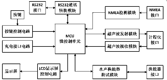
[0039] see figure 1 , a hand-held odometer / transducer tester, the hand-held odometer / transducer tester includes an MCU micro-control unit, an LCD display control circuit, a button control circuit, a charging interface circuit, an ultrasonic receiving module, Ultrasonic transmitter module, underwater acoustic transducer test module, NMEA detection module, RS232 communication conversion module, the LCD display control circuit, button control circuit, charging interface circuit, ultrasonic receiving module, ultrasonic transmitting module, underwater acoustic transducer The test module, NMEA detection module, and RS232 communication conversion module are all connected to the MCU micro control unit, and other circuits and functional modules are controlled by the MCU micro control unit. This technical solution provides a hand-held speed log / transducer tester. When the tester is connected to the speed log, the pulse signal of a certain frequency, width, and peak-to-peak value is tran...
Embodiment 2
[0041] see figure 1, As an improvement of the present invention, the handheld odometer / transducer tester also includes a display screen, buttons, a odometer interface, a transducer interface, an NMEA interface, and an RS232 interface.
[0042] The display screen is connected to an LCD display control circuit, and the LCD display control circuit is used to control the backlight of the display screen;
[0043] The button is connected to a button control circuit, and the button control circuit controls the use of each button on the tester;
[0044] One end of the log interface is connected to the ultrasonic receiving module and the ultrasonic transmitting module, and the other end is used to connect to the log;
[0045] One end of the transducer interface is connected to the underwater acoustic transducer test module, and the other end is used to connect to the transducer;
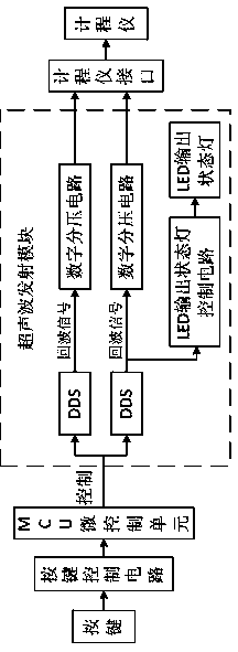
[0046] One end of the NMEA interface is connected to the NMEA detection module, and the other end is use...
Embodiment 3
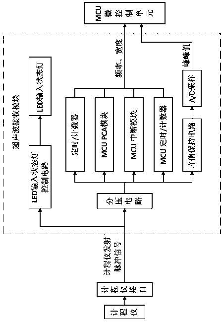
[0052] see figure 2 , as an improvement of the present invention, the ultrasonic receiving module includes LED input status light control circuit, LED input status light, voltage divider circuit, timer / counter, MCU PCA module, MCU interrupt module, MCU timer / counter, peak hold circuit, A / D sampling. The ultrasonic receiving module is used to receive and detect the emission peak value of the speed log and display it on the liquid crystal display; when the tester detects the input of the emission pulse signal, the LED input status light flickers. The input pulse signal, through the voltage divider circuit, attenuates the peak-to-peak value of the input pulse to the range of 0~5V, and then obtains the frequency and width of the input pulse through the timer / counter, MCU PCA module, MCU interrupt module, and MCU timer / counter. The peak-to-peak value of the input pulse is obtained through the peak hold circuit and A / D sampling, and the measured parameter value is displayed on the...
PUM
 Abstract
Description
Claims
Application Information
 - R&D
- Intellectual Property
- Life Sciences
- Materials
- Tech Scout
- Unparalleled Data Quality
- Higher Quality Content
- 60% Fewer Hallucinations
Browse by: Latest US Patents, China's latest patents, Technical Efficacy Thesaurus, Application Domain, Technology Topic, Popular Technical Reports.
© 2025 PatSnap. All rights reserved.Legal|Privacy policy|Modern Slavery Act Transparency Statement|Sitemap|About US| Contact US: help@patsnap.com


