Communication network cabinet

A communication network and network cabinet technology, applied in the direction of cooling/ventilation/heating transformation, etc., can solve the problems of slow heat dissipation, inability to meet the heat dissipation requirements of rows of network cabinets in large computer rooms, insufficient heat dissipation, etc., and achieves reasonable structure and good heat dissipation effect. , the effect of preventing thermal turbulence

Inactive Publication Date: 2014-04-30
NINGBO TIANXIANG COMM EQUIP
View PDF5 Cites 9 Cited by
  • Summary
  • Abstract
  • Description
  • Claims
  • Application Information

AI Technical Summary

Problems solved by technology

This exhaust method has slow heat dissipation and insufficient heat dissipation, which cannot meet the heat dissipation requirements of rows of network cabinets in a large computer room.

Method used


Image

  • Communication network cabinet
  • Communication network cabinet
  • Communication network cabinet

Examples


Embodiment 1

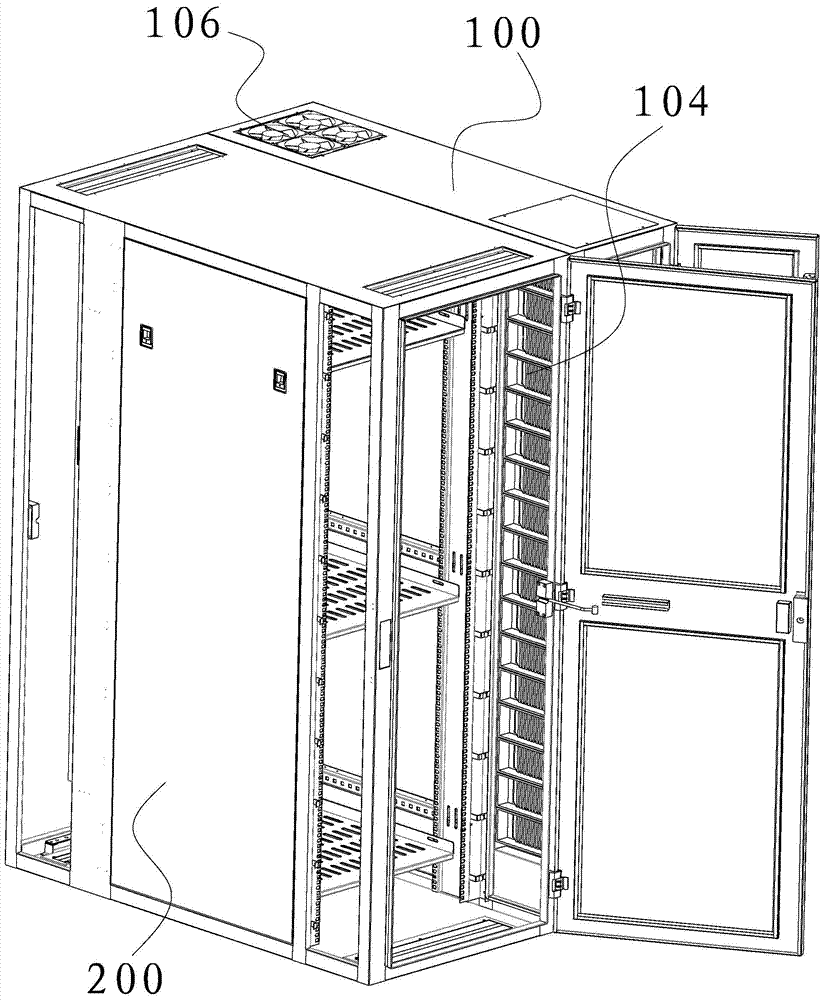
[0028] This preferred embodiment provides a communication network cabinet, such as figure 1 As shown, the communication network cabinet includes a fan cabinet 100 and a network cabinet 200 , and the louvers 104 of the fan cabinet 100 are arranged at the side of the network cabinet 200 .

[0029] The blades of the louvers 104 are movable and adjustable, and the corresponding air supply positions of the louvers 104 can be adjusted according to the installation height of the equipment in the network cabinet 200 . Provide a special channel for the cold air, rationally use the limited cold air resources to achieve better heat dissipation effect, and improve the efficiency of the air conditioner.

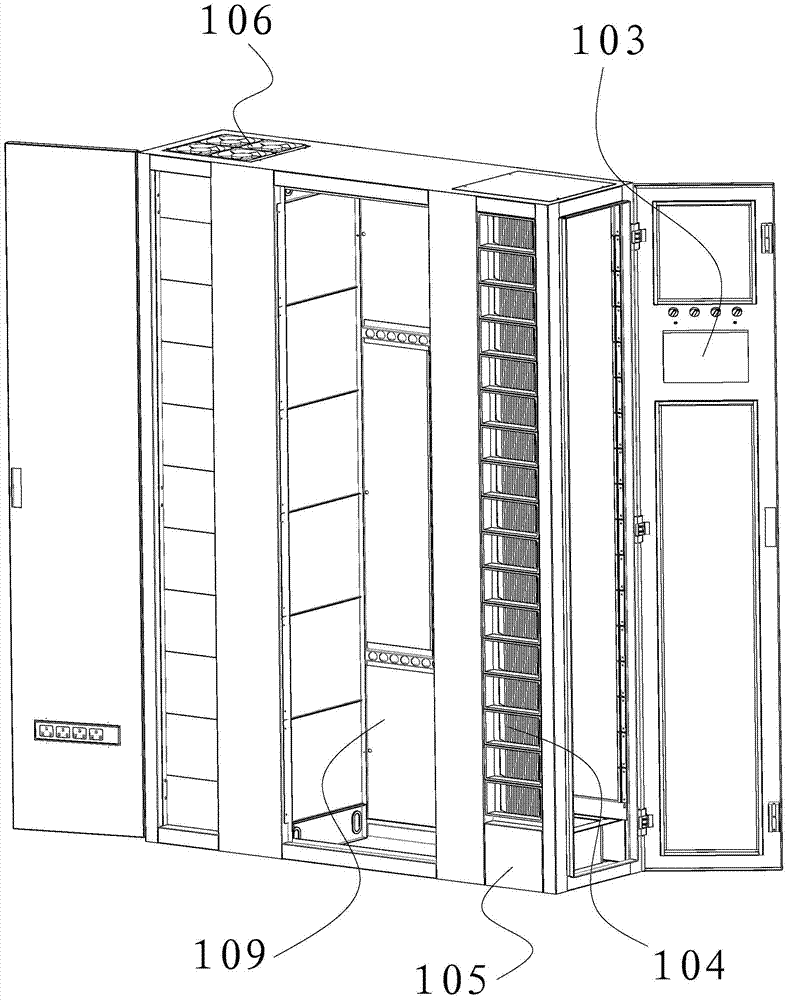
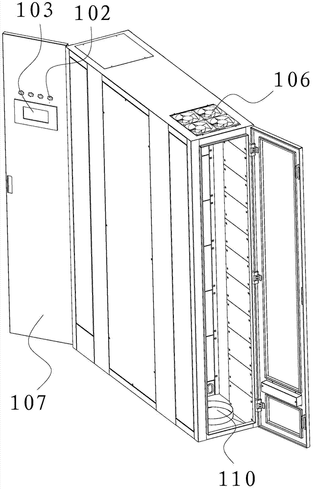
[0030] like figure 2 and image 3 As shown, the air supply cabinet 100 includes an air inlet for sucking in cold air, a return air channel 110 for discharging hot air, and louvers 104 for supplying air.

[0031] The air supply cabinet 100 includes three compartments isolated from each...

Embodiment 2

[0043] This preferred embodiment provides a communication network cabinet, the structure of which is basically the same as that of the first preferred embodiment. The communication network cabinet includes an air supply cabinet and a network cabinet. The air supply cabinet includes an air inlet for sucking cold air, a return air passage for discharging hot air, and louvers for air supply; the louvers of the air supply cabinet are arranged on the network cabinet. The side of the shutter; the blades of the shutters are movable and adjustable.

[0044] The difference is that the communication network cabinet is not limited to include one air supply cabinet and one network cabinet. Two air supply cabinets and one network cabinet can be set up as required. The two air supply cabinets are respectively arranged on both sides of the network cabinet, and the two The shutters of the air supply cabinet are arranged symmetrically with respect to the network cabinet; or one air supply cabi...


PUM


Abstract

The invention discloses a communication network cabinet and belongs to the field of communication equipment. The communication network cabinet is designed for solving the problem that an existing network cabinet is poor in cooling effect. The communication network cabinet comprises at least one air feeder cabinet and at least one network cabinet, wherein the air feeder cabinet comprises an air inlet, an air return channel and a window shutter, the air inlet is used for absorbing cold air into the air feeder cabinet, the air return channel is used for exhausting hot air, and the window shutter is used for feeding air; the window shutter is arranged at the side edge of the network cabinet; leaves of the window shutter are movable and adjustable. The air feeder cabinet comprises three cabins which are insulated from one another, the front cabin is provided with the air inlet and the window shutter, the air return channel is arranged at the bottom of the rear cabin, and the insulation cabin is arranged between the front cabin and the rear cabin and used for insulating the cold air in the front cabin from the hot air in the rear cabin so that thermal turbulent flow between the cold air and the hot air can be avoided. The communication network cabinet is reasonable in structure, good in cooling effect, suitable for various communication working environments, and particularly suitable for the working environment where network cabinets are used in a large machine room side by side in batches.

Description

technical field [0001] The invention relates to a communication network cabinet. Background technique [0002] With the rapid development of communication technology, network cabinets are used more and more. A large number of servers and other heat-generating communication equipment are installed in the network cabinet. In order to ensure a good communication effect, the network cabinet in the large computer room needs to dissipate heat in a timely manner through sufficient exhaust air. [0003] In today's large computer rooms, batches of network cabinets are usually connected side by side, and the network cabinets are radiated through the air inlets and outlets of the air conditioners in the computer room. This exhaust method has slow heat dissipation and insufficient heat dissipation, which cannot meet the heat dissipation requirements of the rows of network cabinets in a large computer room. Contents of the invention [0004] An object of the present invention is to p...

Claims


Application Information

Patent Timeline
IPC IPC(8): H05K7/20
Inventor 胡翱翔金兴弟
Owner NINGBO TIANXIANG COMM EQUIP
Why Eureka
Try Eureka