Vent valve, integrated air pump and electronic sphygmomanometer
A deflation valve and air pressure technology, which can be used in vascular assessment, cardiac catheterization, etc., can solve problems such as inability to use a wearable electronic sphygmomanometer, high power consumption of a solenoid valve with a solenoid valve, and environmental pollution.
- Summary
- Abstract
- Description
- Claims
- Application Information
AI Technical Summary
Problems solved by technology
Method used
Image
Examples
Embodiment 1
[0059] Embodiment 1 provides an air release valve, which includes an upper cover, a lower cover and an elastic body.
[0060] The upper cover has an upper cavity, an air outlet and an air release port, the upper cavity is formed by a sidewall depression on one side of the upper cover, and the air outlet and the air release port communicate with the upper cavity. The lower cover has a lower cavity and an air inlet, the lower cavity is formed by a sidewall depression on one side of the lower cover, and the air inlet communicates with the lower cavity.
[0061] The upper cover and the lower cover are fixedly connected in such a way that the upper cavity and the lower cavity are opposite, and the elastic body is clamped between the upper cover and the lower cover, which divides the upper cavity and the lower cavity into an upper air chamber and a lower air chamber. The elastic body has a vent hole through which the upper air chamber and the lower air chamber communicate.
[0062]...
Embodiment 2
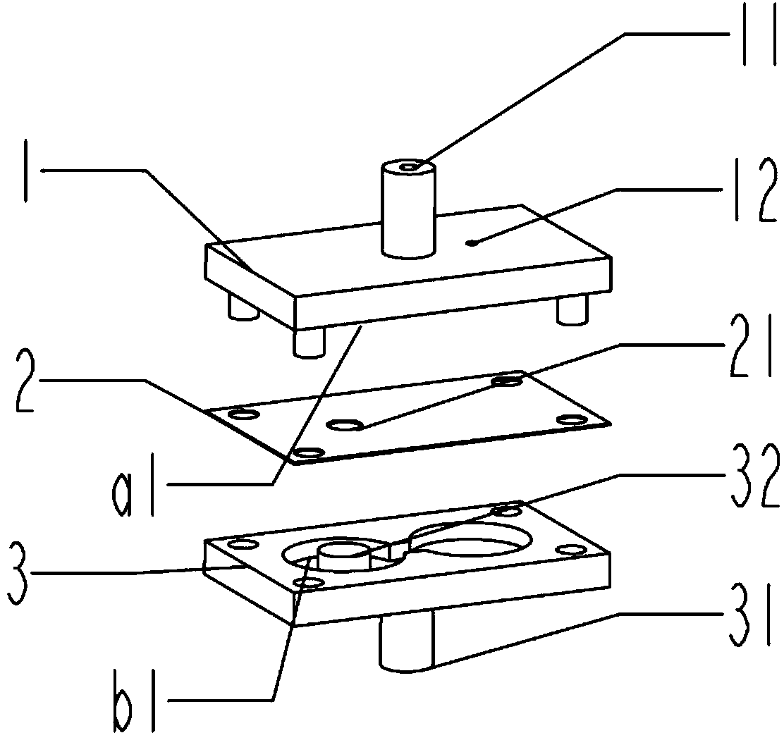
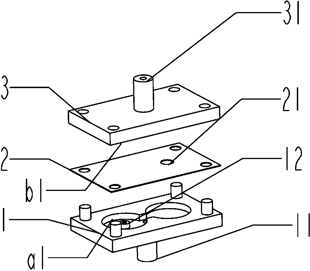
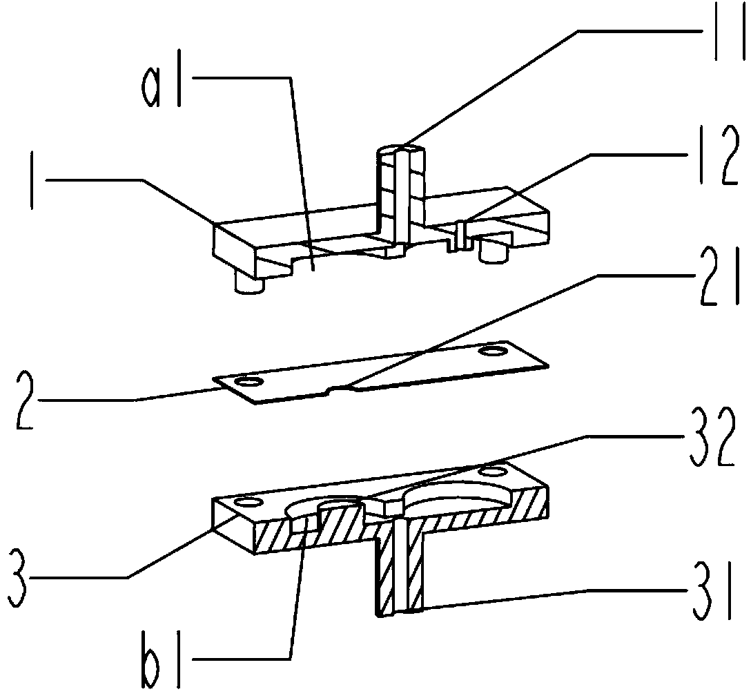
[0066] Please refer to Figure 1-6 , the present embodiment provides a mechanical deflation valve, which specifically includes an upper cover 1 , an elastic body 2 and a lower cover 3 .
[0067] The upper cover 1 has an upper cavity a1, an air outlet 11 and an air release port 12, the upper cavity a1 is formed by a sidewall depression on one side of the upper cover 1, and the air outlet 11 and the air release port 12 communicate with the upper cavity a1. The lower cover 3 has a lower chamber b1 , an air inlet 31 and a boss 32 , the lower chamber b1 is formed by a sidewall depression on one side of the lower cover 3 , and the air inlet 31 communicates with the lower chamber b1 .
[0068] Such as Figure 5 As shown, the upper cover 1 and the lower cover 3 are fixedly connected in such a way that the upper cavity a1 and the lower cavity b1 are opposite, the elastic body 2 is clamped between the upper cover 1 and the lower cover 3, and the upper cavity a1 and the lower cavity Th...
Embodiment 3
[0075] The deflation valve provided by the first embodiment above has a simple structure and is a purely mechanical deflation. Here, it can also be built into an ordinary pressurized air pump, located in the air outlet passage of the air pump, to form an integrated air pump with a rapid deflation function.
[0076] Please refer to Figure 7-11 , the third embodiment provides an example of an integrated air pump based on the above inventive concept.
[0077] The integrated air pump includes a deflation part 100 and a pressurization part 200 . Figure 7-11 The reference numbers starting with the number 1 are all included in the deflation part 100, and the numbers starting with the number 2 are all included in the pressurizing part 200.
[0078] The deflation portion 100 includes such a deflation valve as provided in the present application.
[0079] Specifically, the deflation valve in the third embodiment includes an air nozzle 110 (equivalent to the upper cover 1 in the sec...
PUM
 Abstract
Description
Claims
Application Information
 - R&D
- Intellectual Property
- Life Sciences
- Materials
- Tech Scout
- Unparalleled Data Quality
- Higher Quality Content
- 60% Fewer Hallucinations
Browse by: Latest US Patents, China's latest patents, Technical Efficacy Thesaurus, Application Domain, Technology Topic, Popular Technical Reports.
© 2025 PatSnap. All rights reserved.Legal|Privacy policy|Modern Slavery Act Transparency Statement|Sitemap|About US| Contact US: help@patsnap.com


