Test tube rack with locking function

A test tube rack, test tube technology, applied in the direction of test tube brackets/clamps, etc., can solve problems such as instability, need to be inclined at a large angle to enter, rupture, etc.

Inactive Publication Date: 2014-05-07
林昊
View PDF6 Cites 8 Cited by
  • Summary
  • Abstract
  • Description
  • Claims
  • Application Information

AI Technical Summary

Problems solved by technology

The test tube rack can store a total of 40 test tubes in 8 rows and 5 columns at the same time. If guide columns and springs are arranged in the guide holes at the bottom of the test tube rack, when placing test tubes, it is easier to place the test tubes near the outside of the rack body, and the inclination angle of the test tubes is different. Large, when the test tube is placed in the middle of the test tube rack, the test tube needs to be inclined at a large angle to enter the test tube rack, which requires that the diameter of the guide hole at the bottom of the test tube rack is much larger than the diameter of the test tube, otherwise it is difficult for the bottom of the test tube to enter the guide hole. The increase in the diameter of the guide hole will cause the test tube to be unstable in the test tube rack. Although the test tube is difficult to move up and down under the pressure of the guide column and the spring, the bottom of the test tube will be misaligned. When rotating uniformly, it is very easy to break due to misalignment

Method used


Image

  • Test tube rack with locking function
  • Test tube rack with locking function
  • Test tube rack with locking function

Examples


Embodiment 1

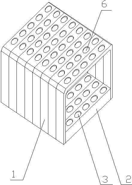
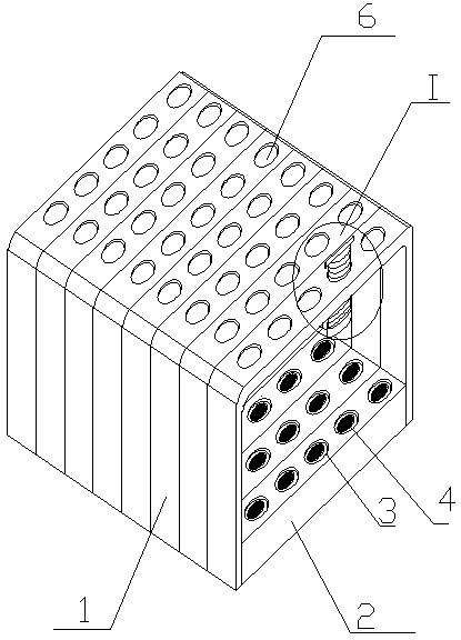
[0027] as attached figure 2 As shown, the test tube rack with locking function is composed of a test tube frame 1 and a test tube support seat 2, the test tube support seat 2 is located at the bottom of the test tube frame 1, and several rows and rows of guide holes 3 are uniformly provided on the test tube support seat 2 . The guide hole has a built-in guide column 4 and the first spring 5, and its structure is shown in the attached Figure 4 shown. The first spring 5 is located at the bottom of the guide hole 3 , and the guide post 4 can freely move up and down in the guide hole 3 under the action of the first spring 5 .

[0028] as attached figure 2 As shown, the top panel of the test tube frame 1 is provided with a through hole 6 corresponding to the guide hole. The through hole 6 and the guide hole 3 are located on the same vertical axis, and the through hole 6 is provided with a test tube locking device.

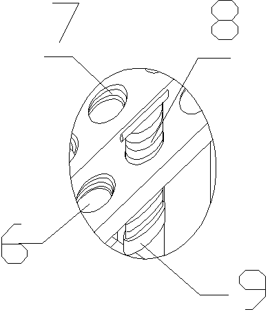
[0029] For the locking device on the through hole 6 see ...

Embodiment 2

[0035] The test tube rack with locking function provided in this embodiment has the same structure except that the locking device is different from that in Embodiment 1.

[0036] as attached Figure 5 shown at II in , for clarity, appended Figure 5 shows a locking device on a through hole, combined with the attached Figure 6 As shown, it should be understood that each through hole 6 is provided with the same locking device.

[0037] as attached Figure 5 , attached Figure 6 , attached Figure 7 and attached Figure 8 As shown, the locking device is a self-locking mechanical switch. The self-locking mechanical switch includes a cylindrical housing 10 fixed on the top panel of the test tube frame. The housing is provided with a top cover 11 and a bottom plate 12 .

[0038] as attached Figure 6 As shown, the through hole 6 is pressed by the bottom plate 12 of the cylindrical shell and is located on the same vertical axis as the cylindrical shell.

[0039] as attached ...


PUM


Abstract

The invention relates to a test tube storage device which aims to solve the technical problems of storage of multiple test tubes in the same test tube rack, and provides a test tube rack with a locking function. The test tube rack consists of a test tube frame and a test tube support seat, wherein the test tube support seat is positioned at the inner bottom of the test tube frame; a plurality of rows and columns of guide holes are uniformly formed in the test tube support seat; guide pillars and first springs are arranged in the guide holes; the first springs are positioned at the bottoms of the guide holes; the guide pillars can freely move up and down in the guide holes under the action of the first springs. The test tube rack is characterized in that through holes corresponding to the guide holes are formed in a panel at the top of the test tube frame, wherein the through holes and the guide holes are positioned in the same perpendicular axes; test tube locking devices are arranged on the through holes. The test tube rack is reasonable in structure and convenient to use, and can be widely applied to transportation, storage and other operation processes of the test tubes.

Description

technical field [0001] The invention relates to a test tube storage device, in particular to a test tube rack with a locking function. Background technique [0002] At present, test tube racks are commonly used in the market. The test tubes cannot be clamped in the rack body, and they are prone to shaking during the transportation process, and they cannot be turned upside down. The safety of the test tubes is difficult to be guaranteed. [0003] Notification number: CN1923369, name: a test tube rack, the test tube rack disclosed in this patent is composed of a test tube frame, a test tube support seat, and a test tube frame bottom plate. The frame and the bottom plate of the test tube frame constitute the outer frame of the test tube rack. The upper part of the test tube frame is provided with several positioning holes for positioning the test tubes. The test tube support seat is provided with several guide holes corresponding to the positioning holes for placing ...

Claims


Application Information

Patent Timeline
Patent Type & Authority Applications(China)
IPC IPC(8): B01L9/06
Inventor 付海英侯水珍
Owner 林昊
Why Eureka
Try Eureka