Method for designing secondary air extraction device

A technology of an air pumping device and a design method, which is applied to mechanical equipment, pumps with flexible working elements, liquid variable capacity machines, etc., can solve the problems of not applying air pumping devices, not considering non-rigid deformation of diaphragm pistons, etc. To achieve a reasonable effect of the design method

Inactive Publication Date: 2014-05-07
JIANGSU UNIV
View PDF4 Cites 3 Cited by
  • Summary
  • Abstract
  • Description
  • Claims
  • Application Information

AI Technical Summary

Problems solved by technology

At present, the existing designs of piston pumps and vacuum pumps have not formed a complete and systematic design method, and there are certain defects in the existing design methods, which are not suitable for the air extraction device involved in the present invention. The non-rigid deformation of the diaphragm piston movement is not considered

Method used


Image

  • Method for designing secondary air extraction device
  • Method for designing secondary air extraction device
  • Method for designing secondary air extraction device

Examples


Embodiment Construction

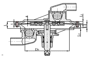
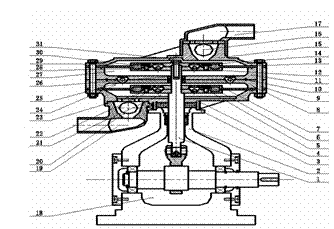
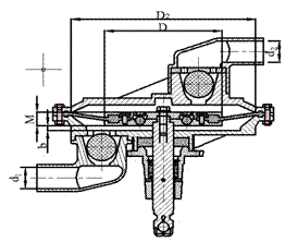
[0108] A secondary air extraction device embodiment of the present invention is such as figure 1 structure shown, figure 1 , figure 2 and image 3 The structure and working principle of an embodiment of a secondary air extraction device designed by the design method provided by the present invention will be described together.

[0109] According to the actual space conditions, the diaphragm pump can be arranged horizontally, vertically and obliquely during operation. combine figure 1 , to describe the embodiment of the secondary air extraction device when it is vertically arranged, and the embodiments in other arrangement states are the same.

[0110] The end of the secondary air extraction device close to the driving mechanism 18 is the first stage low-pressure intake end. The part surrounded by the first-stage upper wall 8 and the first-stage lower wall 4 is the first-stage cavity, and the part surrounded by the last-stage upper wall 15 and the last-stage lower wall 11...


PUM


Abstract

The invention relates to a method for designing a secondary air extraction device. According to the air extraction device, a piston disc is driven by a crank connecting rod to act in a reciprocating mode. Geometrical parameters of the secondary air extraction device are adjusted through a relational expression, wherein the geometrical parameters comprise the internal diameter d1 of a suction tube, the internal diameter d2 of a discharging tube, the diameter D of the piston disc, a gap a between the piston disc and a cavity when air is exhausted in a balanced mode and a gap b between the piston disc and the cavity when air is sucked in a balanced mode. The secondary air extraction device has the advantages of being simple and compact in structure, small in size, high in reliability, good in self-suction performance, convenient to carry, install, overhaul, maintain and repair and the like. The performance of the secondary air extraction device satisfies the requirements for the flow and the maximum vacuum degree of the technology.

Description

technical field [0001] The invention relates to a design method of a two-stage air extraction device, in particular to a design method of an air extraction device which drives a piston disc to reciprocate to perform work through a crank connecting rod. Background technique [0002] The air pump refers to a suction nozzle with one inlet and one outlet, and one exhaust nozzle, and can continuously form a vacuum or negative pressure at the inlet; a slight positive pressure is formed at the exhaust nozzle; the working medium is mainly gas. The working principle of the suction pump is the same as that of the vacuum pump, which is the circular motion of the motor. The diaphragm inside the pump is reciprocated through a mechanical device, thereby compressing and stretching the air in the pump chamber with a fixed volume to form a vacuum (negative Pressure), there is a pressure difference between the pump suction port and the external atmospheric pressure, under the action of the pr...

Claims


Application Information

Patent Timeline
IPC IPC(8): F04B45/04
Inventor 付强王秀礼朱荣生
Owner JIANGSU UNIV
Why Eureka
Try Eureka