

Two-way push-pull chain and reciprocating actuator
A technology of actuating device and push-pull chain, applied in the direction of transmission device, friction transmission device, chain ring, etc., can solve problems such as bulging
- Summary
- Abstract
- Description
- Claims
- Application Information
AI Technical Summary
Problems solved by technology
Method used
Image

Examples
no. 1 approach )
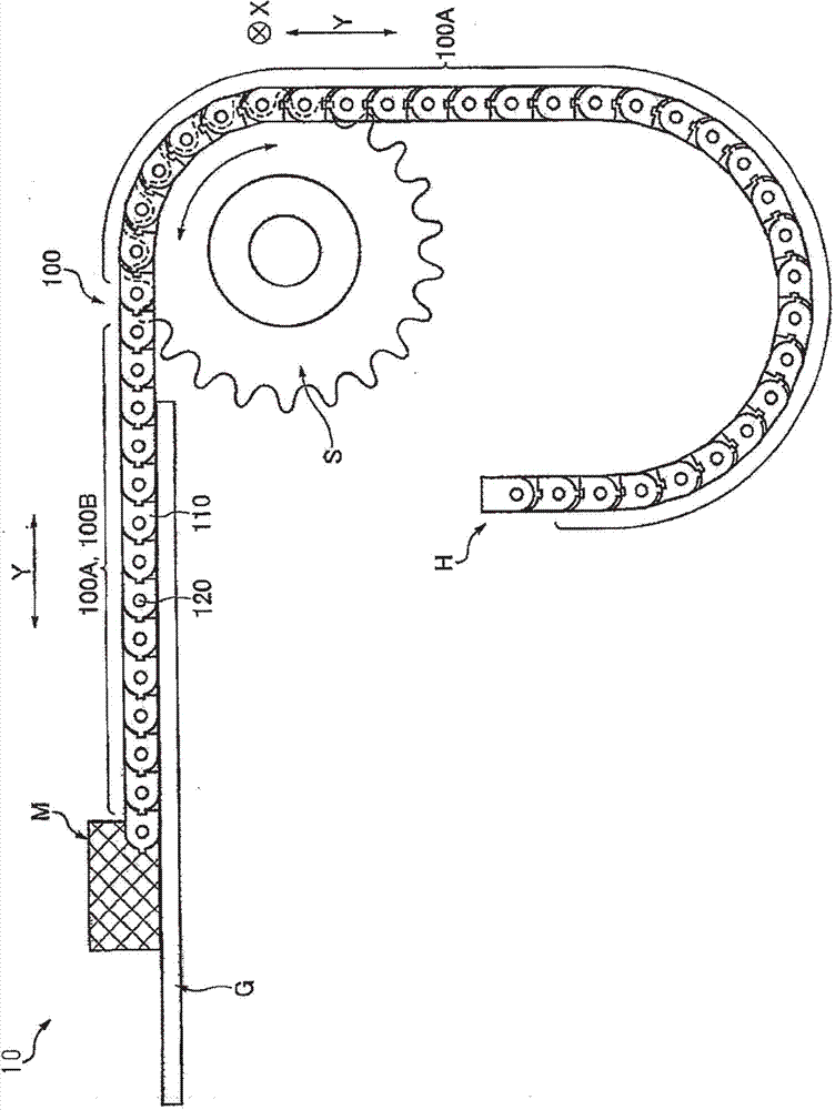
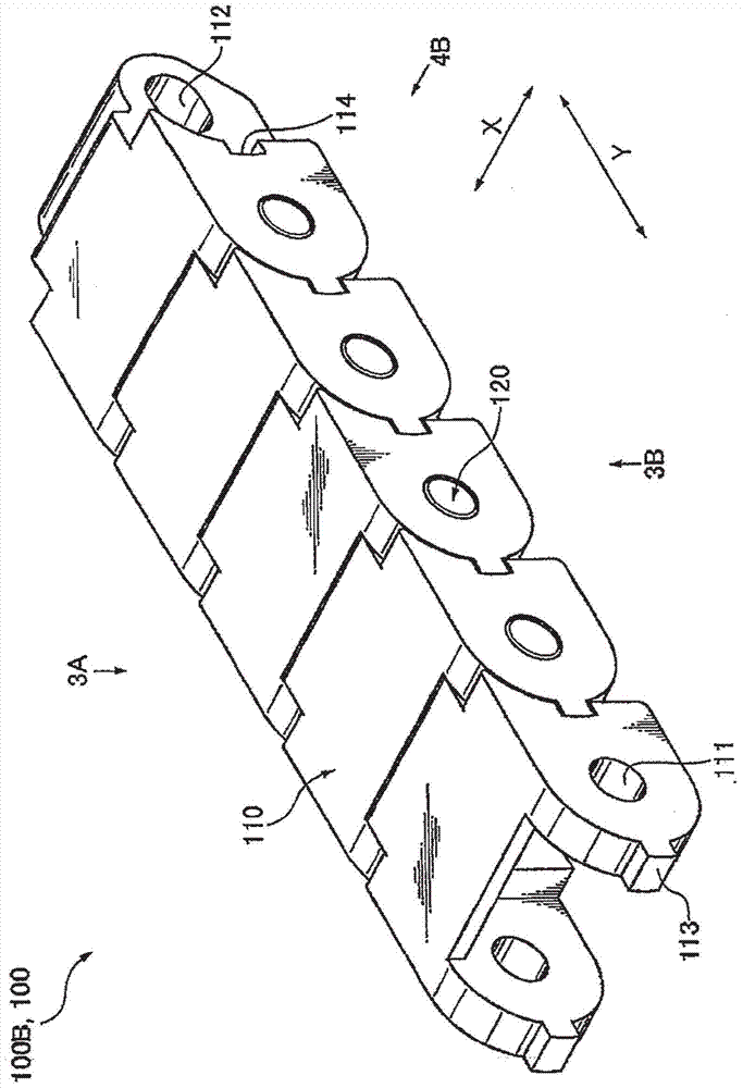
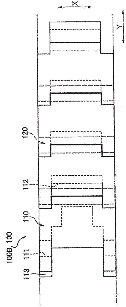
[0021] Below is the reference Figures 1 to 4B Description of the forward and backward actuator 10 and the bidirectional push-pull chain 100 of the forward and backward actuator 10 according to the first embodiment of the present invention. In the following description, the chain longitudinal direction and the chain transverse direction are described as the longitudinal direction Y and the transverse direction X, respectively.
[0022] Such as figure 1 As shown, the forward and backward actuating device 10 includes: a bidirectional push-pull chain 100 , a sprocket S, an actuated part M and a guiding part G. The sprocket S meshes with the two-way push-pull chain 100 to transmit power to the two-way push-pull chain 100 . The actuated part M is attached to the first end of the two-way push-pull chain 100 and moves by the push / pull action of the two-way push-pull chain 100 .
[0023] The guide part G guides the first end of the bidirectional push-pull chain 100 and the actuate...
no. 2 approach )
[0042] Below is the reference Figure 5A and 5B Description of the bidirectional push-pull chain 200 according to the second embodiment of the present invention.
[0043] The two-way push-pull chain 200 reverses the relationship between the depression and the protrusion in the first engaging portion 113 and the second engaging portion 114 of the two-way push-pull chain 100 according to the first embodiment. In the following description of the bidirectional push-pull chain 200, the description of the content common to the bidirectional push-pull chain 100 according to the first embodiment will be omitted, and the last two digits in the reference numerals (200 sequence) of the second embodiment are the same as the first The corresponding reference numerals in the embodiments are the same.
[0044] Such as Figure 5A and 5B As shown, the first engaging portion 213 is a concave portion, and the second engaging portion 214 is a protrusion engaging with the first engaging portio...
no. 3 approach )
[0047] Below is the reference Figure 6A and 6B Description of the bidirectional push-pull chain 300 according to the third embodiment of the present invention.
[0048] The bidirectional push-pull chain 300 changes the shapes of the first engaging portion 113 and the second engaging portion 114 of the bidirectional push-pull chain 100 of the first embodiment. In the following description of the bidirectional push-pull chain 300, the description common to the bidirectional push-pull chain 100 of the first embodiment will be omitted, and the last two digits in the reference numeral (300 sequence) of the third embodiment are the same as those of the first embodiment The corresponding reference signs in are the same.
[0049] Such as Figure 6A and 6B As shown, the first engaging portion 313 is a concave portion, and the second engaging portion 314 is a protrusion engaging with the first engaging portion 313 . Accordingly, the first engaging portion 313 and the second engagi...
PUM
 Abstract
Description
Claims
Application Information