
Detection method of optical element refractivity and detection device thereof
A technology of optical components and detection methods, applied in the direction of testing optical properties, phase influence characteristics measurement, etc., can solve the problems of not representing the refractive index of optical components, inability to prepare samples, devitrification, etc., and achieve convenient use, simple structure, and interference accuracy. high effect
- Summary
- Abstract
- Description
- Claims
- Application Information
AI Technical Summary
Problems solved by technology
Method used
Image

Examples
Embodiment Construction
[0022] The present invention utilizes a Rayleigh interferometer (Rayleigh interferometer), and adopts its characteristics of high double-beam interference precision, simple structure, and convenient use to realize non-destructive high-precision testing of the refractive index of small or special-shaped optical elements.
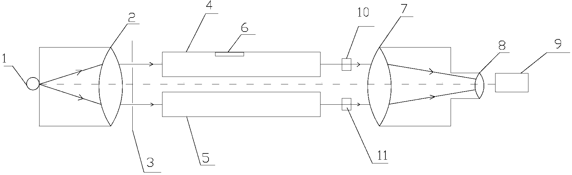
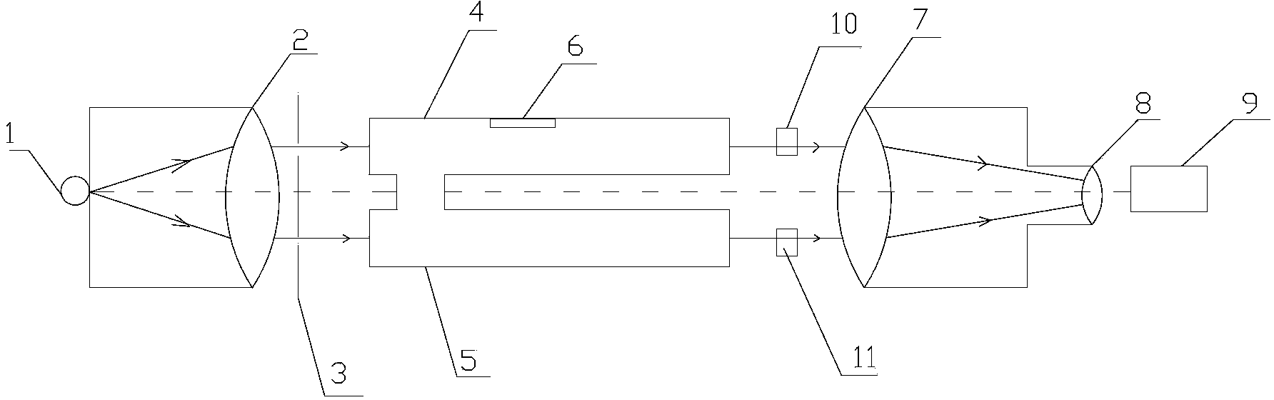
[0023] The detection device of the present invention is followed by the light path in order: light source 1, collimating lens 2, optical slit 3, sample pool, compensator, converging lens 7, cylindrical mirror 8 and observation tube 9, and above-mentioned sample pool comprises the first sample pool 4 and the second sample cell 5, the compensator includes a first compensator 10 and a second compensator 11, and a small hole 6 is opened on the first sample cell 4.
[0024] figure 1 Shown is the optical path diagram of the present invention for detecting the refractive index of small optical elements such as squares and circles with regular shapes and sizes.
[0...
PUM
 Abstract
Description
Claims
Application Information