Cover tap stripping device of carrier band and stripping method

A technology of peeling device and cover tape, applied in the direction of electrical components, electrical components, etc., can solve the problems of the stop of the carrier tape and the inability to enter the carrier tape.

Active Publication Date: 2014-05-07
PANASONIC INTELLECTUAL PROPERTY MANAGEMENT CO LTD
View PDF9 Cites 12 Cited by
  • Summary
  • Abstract
  • Description
  • Claims
  • Application Information

AI Technical Summary

Problems solved by technology

[0006] For example, there is a possibility that the cutting edge of the peeling member cannot enter between the cover tape and the base tape, and the carrier tape in the state where the cover tape is not peeled off may be directly conveyed.
In addition, for example, there is a possibility that the cutting edge of the peeling member comes into contact with the front end surface of the base tape in the tape moving direction to stop the carrier tape.

Method used


Image

  • Cover tap stripping device of carrier band and stripping method
  • Cover tap stripping device of carrier band and stripping method
  • Cover tap stripping device of carrier band and stripping method

Examples


Embodiment Construction

[0036] Hereinafter, embodiments of the present invention will be described with reference to the drawings.

[0037] First, before describing the cover tape peeling device of the carrier tape of the present embodiment, the component supply device which is the premise of the present invention will be described.

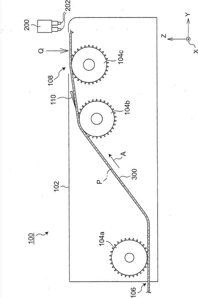
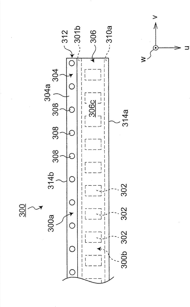
[0038] figure 1 The structure of an example of the components supply apparatus is shown schematically. The component supply device 100 is configured to supply components to the nozzle 202 of the transfer head 200 of the component mounting device. Specifically, the component supply device 100 will figure 2 The illustrated carrier tape 300 accommodating a plurality of components is along the tape conveyance direction A ( figure 2 The tape length direction shown) is sequentially conveyed, and the components accommodated in the carrier tape 300 are supplied to the nozzles 202 of the transfer head 200 at the component supply position.

[0039] figure 2 The front end ...


PUM


Abstract

The present invention provides a cover tape stripping device of a carrier band, which can reliably stripping the cover tape from the carrier band. The cover tape stripping device (10) of the carrier band (300) is stripped from a substrate belt (304) provided with a plurality of receiving parts (302) of elements so as to be bonded on the cover tape (306) on the substrate belt (304) in a manner of covering the receiving parts. The cover tap stripping device has a guide part (20) provided with a reference plane (20a) in abutted connection with a surface (300a) of the carrier band at the cover tape; a blade (16) provided with blade knife points (16a) moving and entering between the cover tape (306) and the substrate belt (304) through the carrier belt (300) in abutted connection in relative to the surface (300a) at the side of the cover tape (306) and the reference plane (20a) of the guide part (20) along the length direction; and a movement limiting part (26) contacting the end face of the substrate belt (304) in the length direction and limiting an entrance amount of the blade (16) between the cover tape (306) and the substrate belt (304) as a ruled amount (L).

Description

technical field [0001] The present invention relates to a device and a method for peeling off a cover tape of a carrier tape. Background technique [0002] Conventionally, a carrier tape has been used to supply components to nozzles of a transfer head of a component mounting apparatus. The carrier tape includes: a base tape in which a plurality of recessed or embossed housing portions for accommodating components are arranged along the tape length direction; and is attached to the base tape so as to cover the multiple housing portions in a state where the components are accommodated cover tape. The cover tape is peeled off from the base tape so that the nozzles of the transfer head of the component mounting device can absorb the components in the storage portion of the carrier tape. [0003] The peeling of the cover tape from the base tape is performed by using a peeling member provided with a knife edge, for example, as in the component supply device described in Patent D...

Claims


Application Information

Patent Timeline
IPC IPC(8): H05K13/02
Inventor 木谷实
Owner PANASONIC INTELLECTUAL PROPERTY MANAGEMENT CO LTD
Why Eureka
Try Eureka