
a hanger

A hanger and hanger technology, which is applied to mountaineering equipment, portable lifting devices, sports accessories, etc., can solve problems such as potential safety hazards, difficulty in self-locking of a figure-eight ring hanger, etc., and achieve simple operation. The effect of convenience and controllable falling speed of the human body

Inactive Publication Date: 2016-12-21
何少敦
View PDF13 Cites 0 Cited by
  • Summary
  • Abstract
  • Description
  • Claims
  • Application Information

AI Technical Summary

Problems solved by technology

[0003] In order to solve the shortcomings of the current 8-shaped ring hanger, which is difficult to self-lock and has certain safety hazards during use

Method used


Image

  • a hanger
  • a hanger
  • a hanger

Examples


Embodiment Construction

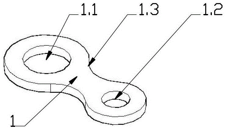
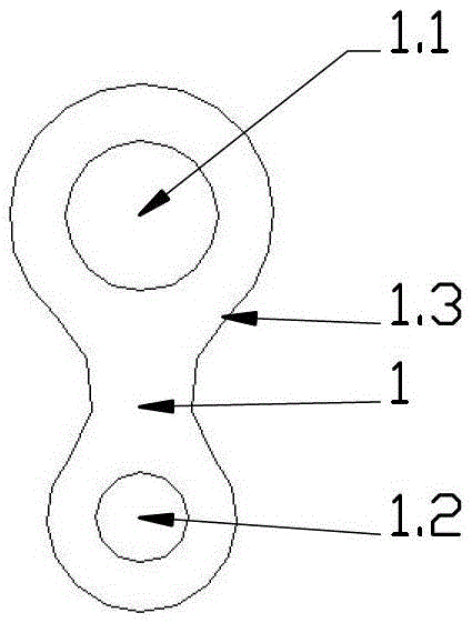
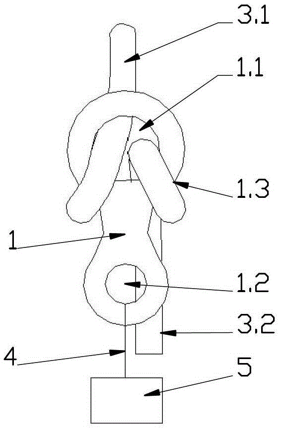
[0040] figure 1 , figure 2 , image 3 is the structural schematic diagram of the existing 8-shaped ring type hanger; figure 1 is a schematic diagram of the three-dimensional structure, figure 2 Plane structure diagram, image 3 It is a schematic diagram of the structure in use.

[0041] figure 1 , figure 2 Shown in, the existing figure-of-eight ring type hanger is made of the hanging body 1 that has roping hole 1.1, hanging hole 1.2.

[0042] image 3 It is a schematic diagram of the structure in use, image 3 It shows that when in use, the working rope passes through the rope-threading hole 1.1 and is sleeved on the waist 1.3 of the hanging body, the fixed end 3.1 of the working rope is fixed at a high place through the rope-threading hole 1.1, and the free end 3.2 of the working rope passes through the rope-threading hole 1.1 hangs down to a low position, and the human body 5 is connected and fixed with the lifting hole 1.2 through the connecting piece 4 . When ...


PUM


Abstract

A variable cross-section rope winding wheel comprises a wheel body (6.1) and an installation hole (6.2). The rope winding wheel is provided with a variable cross-section rope groove. When a rope is wound on different positions of the rope winding wheel groove, the friction force between the rope and the rope winding wheel groove is also different. A suspension device with the variable cross-section rope winding wheel is provided. A U-shaped rope penetrating part (2) is arranged on a suspension body (1) of the suspension device. A rope penetrating hole (1.1) is formed by a U-shaped opening of the U-shaped rope penetrating part (2) and the suspension body. The variable cross-section rope winding wheel is arranged on the suspension body. A suspension hole (1.2) bearing human body weight is arranged at a position deviating towards one side. A suspension body control handle (1.4) for controlling the deflection of the suspension device is arranged on the other side of the suspension hole. When the variable cross-section rope winding wheel is used, an operation rope passes through the rope penetrating hole and then is wound on the variable cross-section rope winding wheel. One end of the operation rope is fixed, and the other end of the operation rope hangs down to a lower position. A human body is fixedly connected with the suspension hole. When a human body is born and hung by the suspension hole alone, due to the fact that the fixed end of the operation rope and a free end thereof are mutually tightly compressed, the suspension device is in a self-locking state. When the human body applies pull to the suspension device through the control handle, the deflection of the suspension device happens, the rope begins to slide, the variable cross-section rope winding wheel is controlled to rotate by hand, and the friction between the rope winding wheel and the rope can be adjusted to control the descending speed. The devise solves the problem that an 8-shaped ring type suspension device in the prior art is difficult in self-locking.

Description

technical field [0001] The invention relates to a hanger, in particular to a hanger which uses the weight of the human body as gravity and is manually controlled. Background technique [0002] The current 8-shaped ring hanger is characterized by simple structure and easy operation, so it is widely used in rock climbing, caving, aerial work, high-altitude rope descent, etc. The disadvantage of the existing 8-shaped ring hanger is that it is self-locking There are difficulties, people must apply continuous pulling force to the free end of the working rope to control the descent speed, if it is necessary to hover in the air for a long time, the free end of the working rope must be fixed; therefore, due to the inconvenience in operation, for For those who have not received professional training, there are certain potential safety hazards in using the existing 8-shaped ring type hanger. Contents of the invention [0003] In order to solve the disadvantages of difficulty in sel...

Claims


Application Information

Patent Timeline
Patent Type & Authority Patents(China)
IPC IPC(8): A62B35/00A62B1/14A62B1/18A63B29/02
CPCA62B1/14B66D3/02
Inventor 何少敦
Owner 何少敦
Learn More