
Fan Component Forming Device

A molding device and component technology, applied in coating and other directions, can solve problems such as limited depth, limited number of metal components, and increased labor costs, and achieve the effects of improving quality, reducing water marks, and improving yield

Active Publication Date: 2016-06-29
SUNON ELECTRONICS KUNSHAN
View PDF3 Cites 0 Cited by
  • Summary
  • Abstract
  • Description
  • Claims
  • Application Information

AI Technical Summary

Problems solved by technology

In addition, it is also possible that the high-temperature male mold and the female mold accidentally touch the operator while touching the mold clamping control key of the fan component molding device, or when an electrical failure occurs temporarily in the mold clamping control. Therefore, the operation safety of the existing fan component molding device is not good, and the operator cannot operate quickly in order to take into account the safety of the operation, and the efficiency of manufacturing the fan component cannot be improved.
[0005] Furthermore, when the existing fan component molding device intends to increase the number of fan components formed each time, and increase the positioning seats and filling grooves on the male mold and the female mold, since the operator moves his hands from one side of the machine, The depth of insertion into the mold is limited, and the number of metal components that can be placed each time is also limited, so that each fan component forming device needs to be equipped with an operator on both sides, so that the fan components can be manufactured more efficiently. Therefore, the burden of human cost is increased

Method used


Image

  • Fan Component Forming Device
  • Fan Component Forming Device
  • Fan Component Forming Device

Examples


Embodiment Construction

[0053] In order to make the above-mentioned and other objects, features and advantages of the present invention more comprehensible, the preferred embodiments of the present invention are specifically cited below, together with the accompanying drawings, as follows:

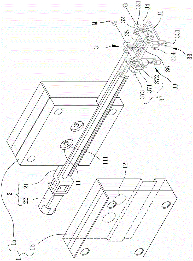
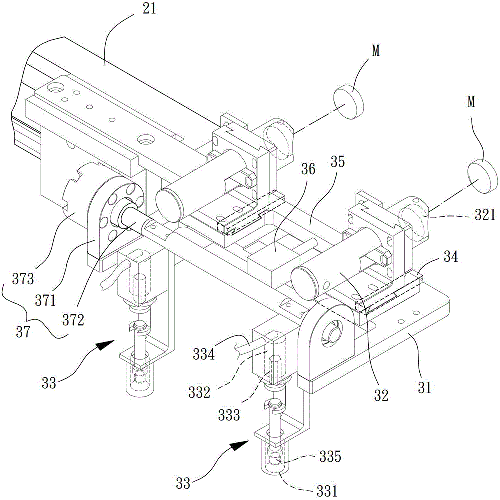
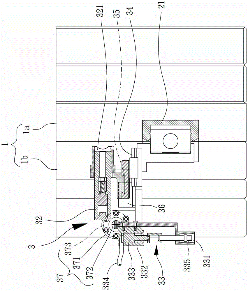
[0054] Please refer to figure 1 , which discloses a fan component forming device according to a preferred embodiment of the present invention. In this embodiment, the fan component forming device may include a mold set 1, a moving component 2 and a conveying component 3, and the moving component 2 is adjacent to the The mold set 1 and the conveying assembly 3 are movably arranged on the travel assembly 2 to move into or out of the mold set 1 . Wherein, the fan component molding device can be used to manufacture components composed of metal materials and plastic materials. For example, fan wheels comprising metal sealing magnets and plastic fan blades, fan frames comprising metal bottom plates and plastic side wal...


PUM


Abstract

The invention discloses a fan component forming device. The fan component forming device comprises a die assembly, a moving assembly and a conveying assembly, wherein the moving assembly is arranged near the die assembly; the conveying assembly is movably arranged in the moving assembly so as to move in or out of of the die assembly. Accordingly, the fan component forming device is capable of putting a sealed magnet in the die by the conveying assembly, so that effects of conveniently operating and improving the operation safety can be achieved.

Description

technical field [0001] The invention relates to a fan component molding device, in particular to a fan component molding device for manufacturing cooling fan components through injection molding. Background technique [0002] At present, many components of cooling fans are composed of metal materials and plastic materials, such as fan wheels, fan frames, or stator groups; among them, when the existing fan components are manufactured by injection molding, the used The fan component molding device generally includes a male mold and a female mold that can be opened and closed mutually. A surface of the male mold is provided with several positioning seats, and a positioning part is respectively provided in the middle of each positioning seat. One of the female molds The surface is recessed with several filling grooves; during operation, several metal components are manually placed into the positioning seats on the periphery of several positioning parts of the male mold, and then...

Claims


Application Information

Patent Timeline
Patent Type & Authority Patents(China)
IPC IPC(8): B29C45/14B29C45/26B29C45/42B29C31/08
CPCB29C45/14032B29C45/14065B29C45/26B29C45/42
Inventor 赖进龙
Owner SUNON ELECTRONICS KUNSHAN
Learn More