
Paper stacking method applied to paper processing device

A paper processing device and paper technology, applied in the field of stacking paper, can solve the problems of reducing the paper load capacity of the tray, paper stacking failure, labor-intensive finishing, etc.

Inactive Publication Date: 2014-05-14
PRIMAX ELECTRONICS LTD
View PDF7 Cites 0 Cited by
  • Summary
  • Abstract
  • Description
  • Claims
  • Application Information

AI Technical Summary

Problems solved by technology

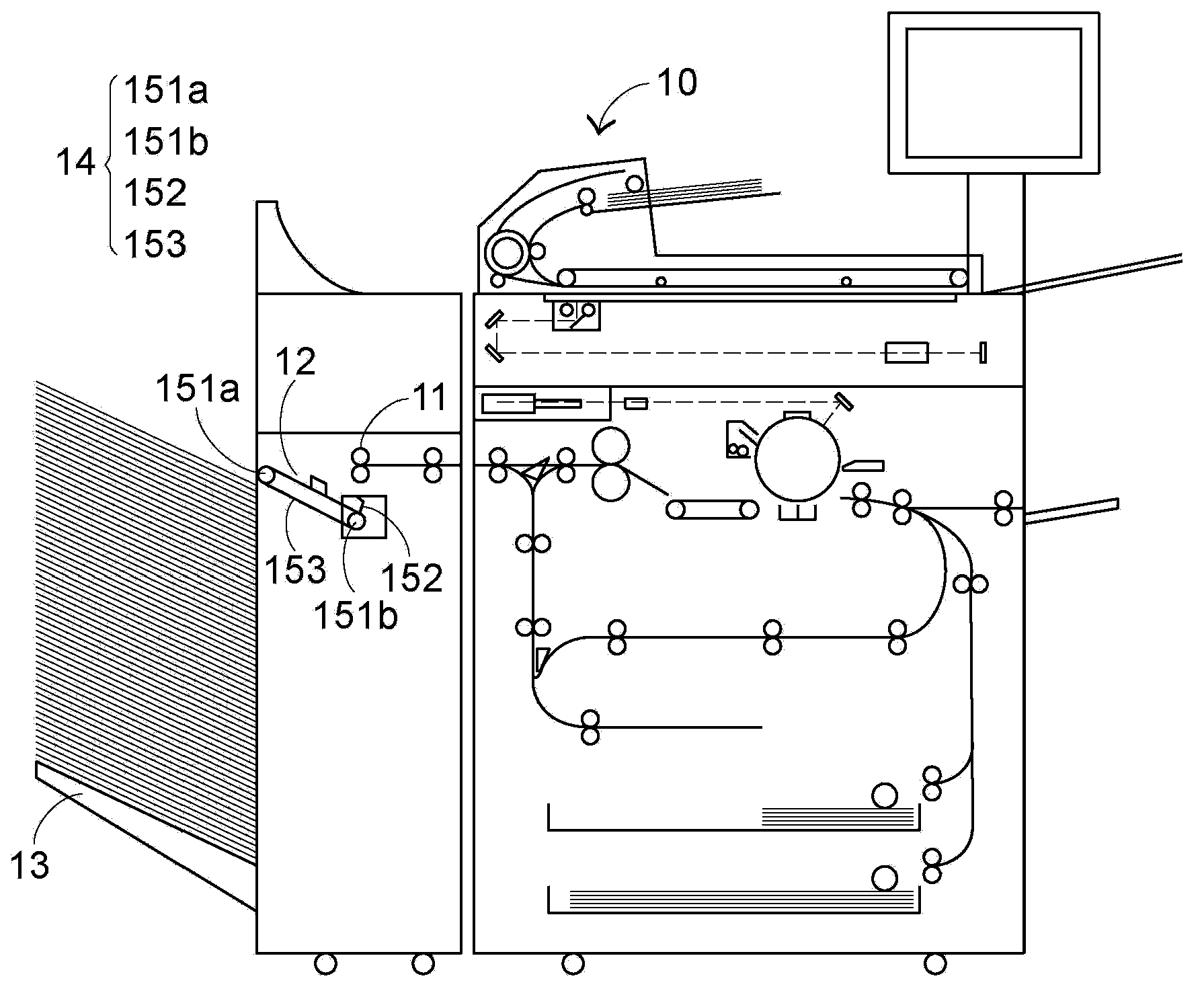
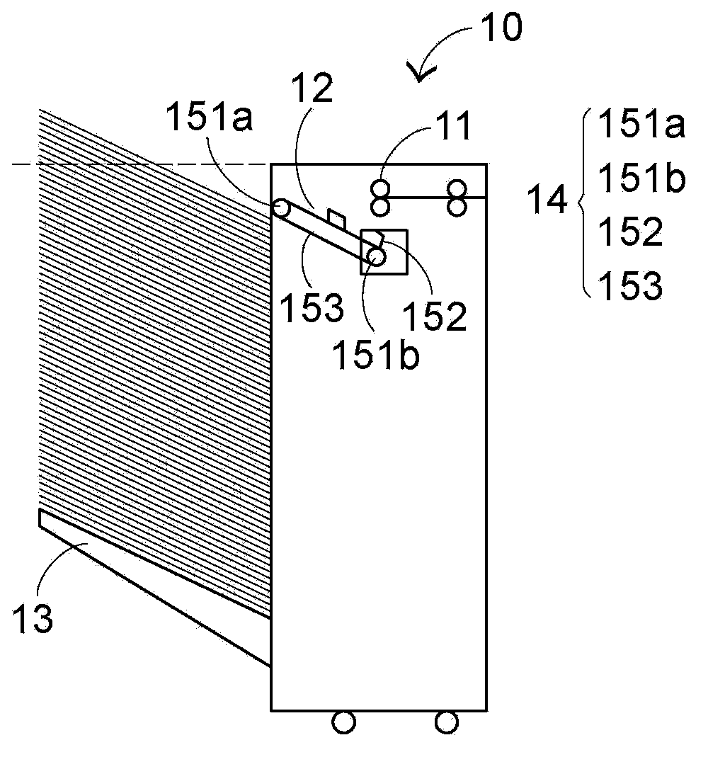
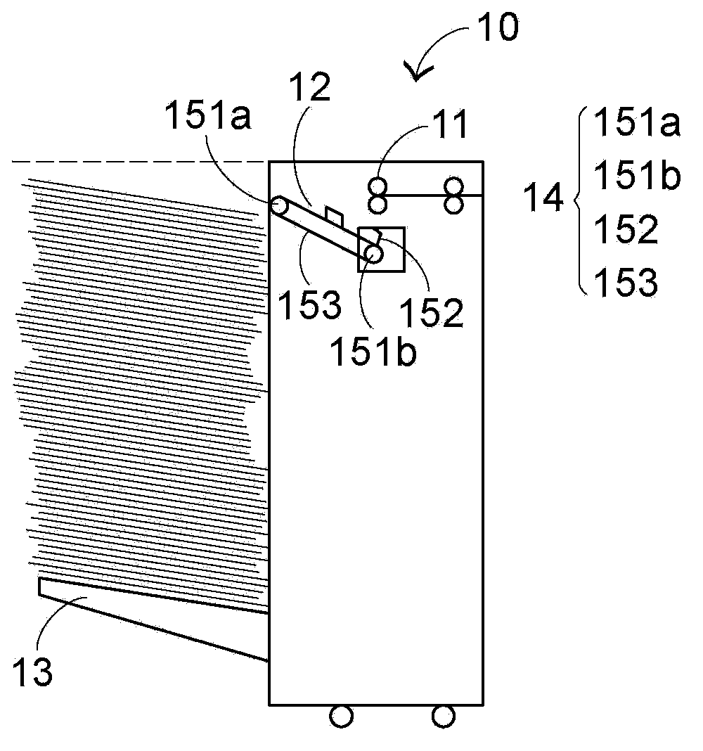
However, as the angle between the paper tray 13 and the paper processing device 10 increases, the scattering phenomenon caused by a plurality of papers falling from the platform 12 becomes more serious.
Scattered multiple sheets of paper not only require extra manpower to organize and reduce work efficiency, but also easily cause paper stacking failure, thereby reducing the paper loading capacity of the paper tray

Method used


Image

  • Paper stacking method applied to paper processing device
  • Paper stacking method applied to paper processing device
  • Paper stacking method applied to paper processing device

Examples


Embodiment Construction

[0063] Please refer to Figure 4 and Figure 5 , Figure 4 is a schematic diagram of the first embodiment of the paper processing device of the present invention, Figure 5 It is a block diagram of the paper processing device of the present invention. like Figure 4 and Figure 5 As shown, the paper processing device 20 includes a platform 21, a paper tray 22, a transmission mechanism 23, a paper presser 24, a controller 25, a first sensor 26, a second sensor 27 and A third sensor 28 , wherein the first sensor 26 , the second sensor 27 and the third sensor 28 are electrically connected to the controller 25 for sending an electrical signal to the controller 25 . In addition, the controller 25 is electrically connected to a power source (not shown in the figure), such as a DC motor, for driving the paper tray 22 and the transmission mechanism 23 .

[0064] read on Figure 4 . The platform 21 is located at the paper outlet of the paper processing device 20 , and is used f...


PUM


Abstract

The invention provides a paper stacking method applied to a paper processing device. The paper processing device comprises a platform, a paper pallet and a push rod. The paper stacking method includes that the push rod perpendicularly penetrates the platform, moves along the platform and is used for pushing a plurality of pieces of paper on the platform to the paper pallet; the paper pallet is arranged on downstream of the platform and is initially positioned on a moving path of the push rod, so that the distance from the platform to the paper pallet can be shortened. The paper stacking method has the advantage that the multiple pieces of paper can be prevented from flying around, and can be neatly stacked by the aid of the paper stacking method.

Description

technical field [0001] The invention relates to a method for stacking paper, in particular to a method for improving the phenomenon of paper flying generated when a paper processing device stacks paper. Background technique [0002] Paper handling devices capable of copying, scanning, faxing, stapling and / or printing documents are common office machines. see figure 1 as shown, figure 1 It is the first schematic diagram of the existing paper processing device. like figure 1 As shown, the paper processing device 10 includes a paper outlet 11 , a platform 12 , a paper tray 13 and a transmission mechanism 14 . The transmission mechanism 14 includes two driving wheels 151 a, 151 b, a belt 152 and a push rod 153 . [0003] The platform 12 is disposed on one side of the paper outlet 11 for receiving a plurality of papers fed out of the paper processing device 10 . The paper tray 13 is disposed downstream of the platform 12 and is used for carrying a plurality of papers from t...

Claims


Application Information

Patent Timeline
Patent Type & Authority Applications(China)
IPC IPC(8): B65H29/38B65H31/26B65H31/00
Inventor 吴家汶王庆泽
Owner PRIMAX ELECTRONICS LTD
Learn More