Switch test system and switch test method

A technology of a test system and a test method, which is applied in transmission systems, digital transmission systems, data exchange networks, etc., can solve problems such as the inability to monitor the data packet sending and receiving performance of multiple switches in real time, and achieve the effect of improving efficiency and

Inactive Publication Date: 2014-05-14
PHICOMM (SHANGHAI) CO LTD
View PDF5 Cites 14 Cited by
  • Summary
  • Abstract
  • Description
  • Claims
  • Application Information

AI Technical Summary

Problems solved by technology

[0003] The technical problem to be solved by the present invention is to overcome the defect that the data packet sending and receiving performance of multiple switches cannot be directly monitored in real time in the prior art, and propose a switch testing system and a switch testing method utilizing the switch testing system, by setting A host computer, a data output module, a data input module and a relay module, the relay module is controlled by the control command issued by the host computer, so as to realize real-time monitoring of the data packet sending and receiving performance of multiple switches

Method used


Image

  • Switch test system and switch test method
  • Switch test system and switch test method

Examples


Embodiment 1

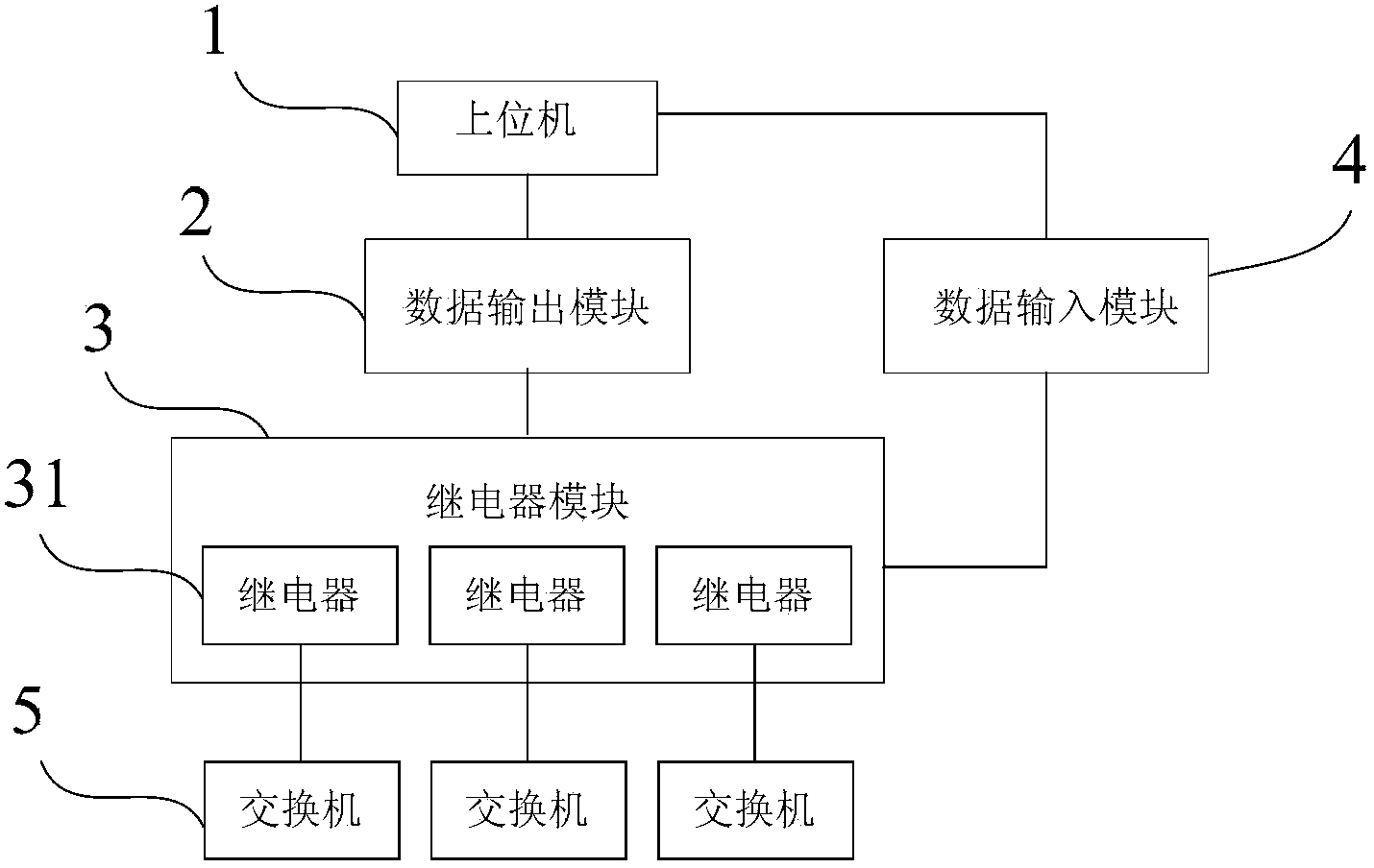
[0025] Such as figure 1 As shown, the switch test system of this embodiment includes a host computer 1, a data output module 2, a data input module 4 and a relay module 3, and the relay module 3 includes a plurality of relays for connecting a plurality of switches 5 31, the data output module 2 is connected to the host computer 1 and the relay module 3, and is used to control the conduction or disconnection of the plurality of relays 31 according to the preset state contained in a control command sent by the host computer 1, the The data input module 4 is used to read the on-off status of the plurality of relays 31 and send it to the host computer 1, and the host computer 1 is used to send a PING command to the plurality of switches 5 to check the status of the plurality of switches 5 respectively. Packet sending and receiving performance.

[0026] Wherein the upper computer 1 is a computer, and the data input module 4 and the data output module 2 are respectively a micro con...

Embodiment 2

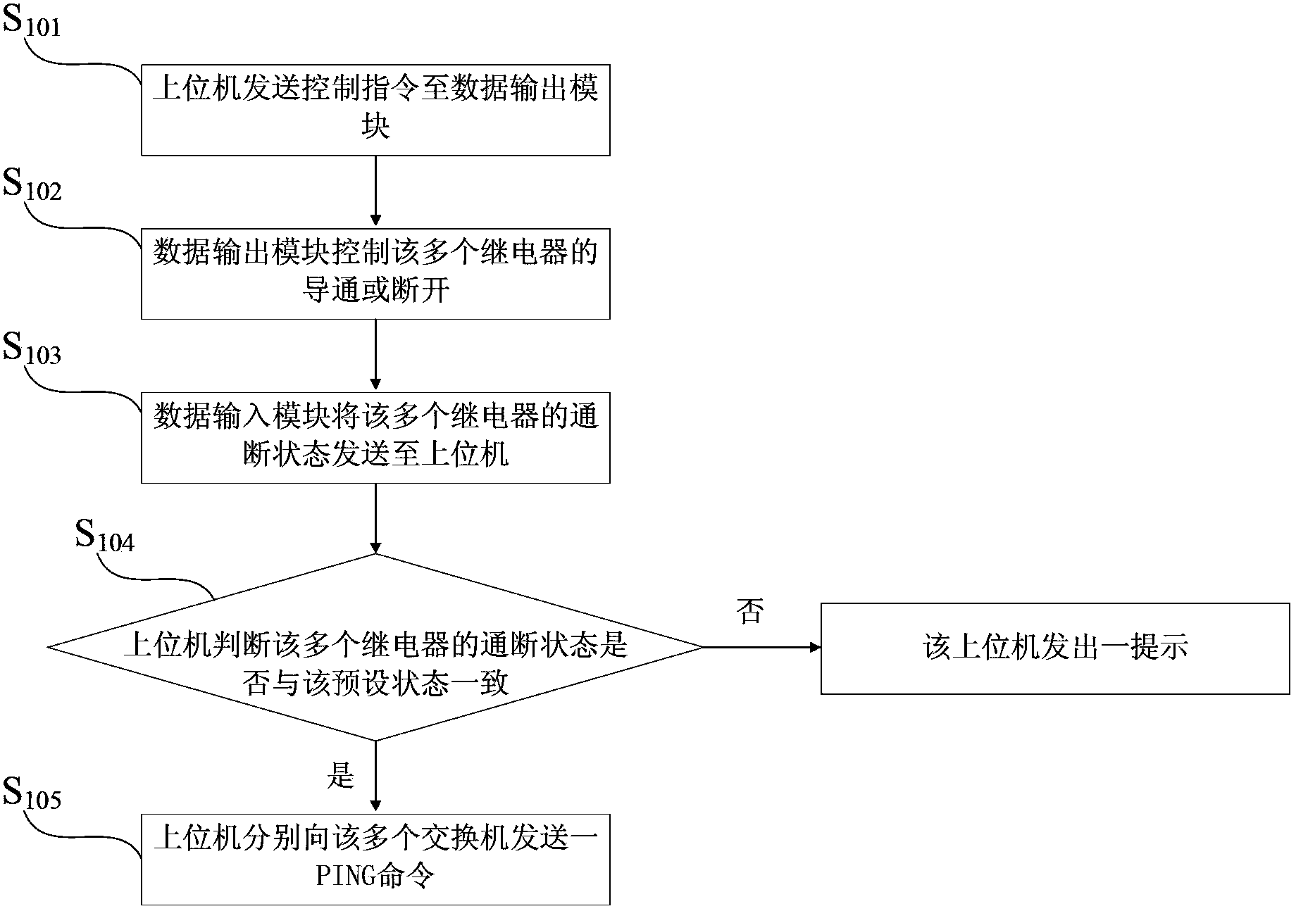
[0030] Such as figure 2 As shown, the switch 5 testing method of the present embodiment utilizes the switch testing system of Embodiment 1, and the switch 5 testing method includes the following steps:

[0031] S 101 . The upper computer 1 sends the control command to the data output module 2;

[0032] S 102 . The data output module 2 controls the conduction or disconnection of the plurality of relays 31;

[0033] S 103 . The data input module 4 reads the on-off status of the plurality of relays 31 and sends it to the host computer 1;

[0034] S 104 , the host computer 1 judges whether the on-off state of the plurality of relays 31 is consistent with the preset state, and when the judgment result is yes, enter step S 105 , when the judgment result is no, the host computer 1 sends a prompt, and the process is terminated;

[0035] S 105 1. The host computer 1 sends a PING command to the plurality of switches 5 to check the data packet sending and receiving performance o...


PUM


Abstract

The invention discloses a switch test system and a switch test method. The switch test system comprises an upper computer, a data output module, a data input module and a relay module. The relay module comprises multiple relays. The data output module is connected with the upper computer and the relay module and used for controlling on or off of the multiple relays according to the preset state contained in a control instruction sent by the upper computer. The data input module is used for reading the on-off state of the relays and sending the on-off state to the upper computer. The upper computer is used for sending a PING command to a switch to detect performance of the switch. According to the switch test system and the switch test method utilizing the switch test system, the relay module is controlled via the control instruction sent by the upper computer so that receiving and sending performance of data packets of multiple switches can be monitored in real time, and efficiency in a switch performance test and reliability in a test result are enhanced.

Description

technical field [0001] The invention relates to an exchange testing system and an exchange testing method. Background technique [0002] The data packet sending and receiving of the switch is its basic function. In the production process of switches, the high temperature aging test of products is an important test process to improve the reliability of switch products and ensure the stable performance of products under extreme conditions. The high temperature aging test of the product has strict test standards, usually the test environment temperature should reach 50±5℃. The product is in working condition during the aging test. In the prior art, real-time monitoring of the operating temperature and output voltage parameters of the product is used to diagnose whether the product is faulty during the aging process, so as to improve the quality and reliability of the product, but such detection requires a lot of manpower to check the parameters of the switches one by one. Th...

Claims


Application Information

Patent Timeline
Patent Type & Authority Applications(China)
IPC IPC(8): H04L12/26H04L12/931
Inventor 蒋刚
Owner PHICOMM (SHANGHAI) CO LTD
Why Eureka
Try Eureka