
Connection device

A technology of connecting device and positioning part, applied in the direction of fixing device, mechanical equipment, etc., can solve the problems of destroying the structure and appearance of the protective cover and related plastic parts, inconvenient for users to replace the protective cover, and the soft protective cover is not easy to connect, etc. To achieve the effect of simple and ingenious mechanism, quick disassembly and assembly operation

Inactive Publication Date: 2014-05-21
HONG FU JIN PRECISION IND (SHENZHEN) CO LTD +1
View PDF0 Cites 3 Cited by
  • Summary
  • Abstract
  • Description
  • Claims
  • Application Information

AI Technical Summary

Problems solved by technology

[0003] However, the soft protective cover is usually not easy to connect with the relevant plastic parts of the electronic product. The connection between the existing soft protective cover and the relevant plastic parts of the electronic product is usually glued, ultrasonic welding, hot-melt welding or seaming, etc. connection method
However, for electronic products using the above-mentioned connection methods, the mold opening of the relevant plastic parts and the assembly process of the plastic parts and the protective cover are relatively complicated. The repair of defective products will destroy the structure and appearance of the protective cover and related plastic parts, and it is not convenient for users. Change the protective cover at any time according to your own preferences

Method used


Image

  • Connection device
  • Connection device
  • Connection device

Examples


Embodiment Construction

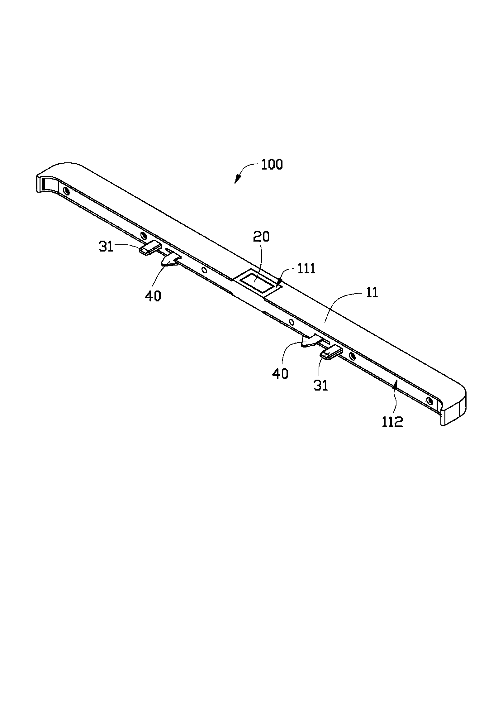
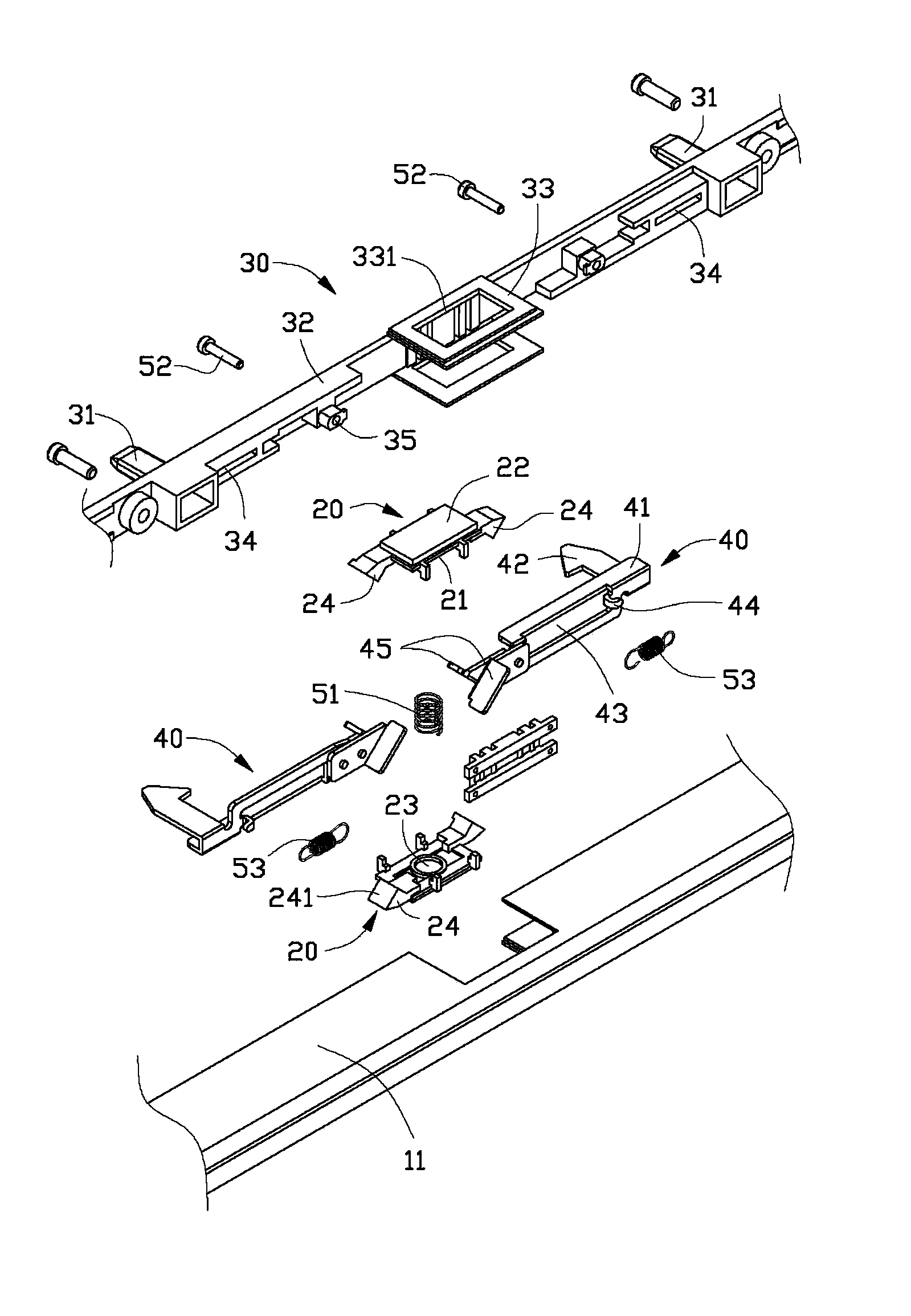
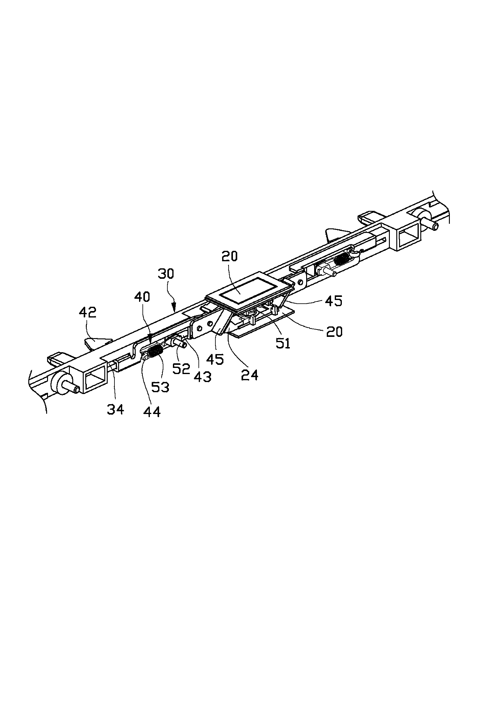
[0019] see figure 1 , provide a connection device 100, including a housing 11 and at least one pressing member 20, a pair of positioning posts 31 and a pair of hook members 40 disposed in the housing 11, wherein at least one of the housing 11 A mounting hole 111 is formed on the surface, and the pressing member 20 is located in the mounting hole 111 . Two positioning posts 31 and two hooks 40 protrude from a side edge 112 of the casing 11 .

[0020] The side edge 112 of the housing 11 protruding from the two hooks 40 has a side edge matching with the side edge of an electronic device (not shown in the figure, such as but not limited to a mobile phone, a tablet computer, an e-book, a netbook, a PDA, etc.). shape. In this embodiment, the electronic equipment used in conjunction with the connecting device 100 is provided with a positioning hole (not shown) matching with the two positioning posts 31 and a sliding slot (not shown) matching with the two hook members 40 on its side...


PUM


Abstract

The invention discloses a connection device, which comprises a cover plate, at least one pressing element and two grabbing elements, wherein the cover plate comprises a stationary shaft and two positioning parts which protrude from the inner side of the stationary shaft; at least one positioning part is provided with a through hole; the pressing element comprises a shoulder, a pressing part extruded from the shoulder and one pair of contact arms which extend outwards from two ends of the shoulder; the tail end of each contact arm is provided with a contact slope; the pressing part is contained in the through hole of the corresponding positioning part; the contact arm is abutted against the inner side of the positioning part; a first elastic element is arranged between the two positioning parts; at least one end of the first elastic element is abutted against the pressing element; the two grabbing elements are installed on the cover plate and are positioned on two sides of the positioning part; each grabbing element comprises a main body, a hook and at least one inclined guide sheet, wherein the hook vertically extends out from one end of the main body; each guide sheet is abutted against one corresponding contact slope. The connection device disclosed by the invention has the advantages of simple and artful mechanism, and simple and quick assembling and disassembling operation with two objects connected with the connection device can be realized.

Description

technical field [0001] The invention relates to a connecting device. Background technique [0002] With the advancement of technology, various portable electronic products, such as mobile phones, tablet computers, and PDAs, have become popular. Most of these electronic products are fashionable in appearance, beautiful in shape and increasingly powerful in function. They not only become a tool in people's daily life, but also become fashion accessories and even status symbols that people carry at any time. However, if you do not pay attention to use, If it is placed randomly, its appearance will be easily scratched. Therefore, people usually add a soft protective cover to the surface of the electronic product casing. [0003] However, the soft protective cover is usually not easy to connect with the relevant plastic parts of the electronic product. The connection between the existing soft protective cover and the relevant plastic parts of the electronic product is usually gl...

Claims


Application Information

Patent Timeline
IPC IPC(8): F16B1/00
Inventor 李文泰吴才华张振忠詹德盛
Owner HONG FU JIN PRECISION IND (SHENZHEN) CO LTD
Learn More