Hydraulic gripper for gas extraction, drainage and discharge driller

A hydraulic clamping and drilling rig technology, which is applied in the direction of gas discharge, drill pipe, drill pipe, etc., can solve the problems of unreliable clamping, inconsistent drill pipe center, increased drilling rig vibration, etc. Adjustable, clamping and reliable results

Inactive Publication Date: 2010-11-03
CHONGQING UNIVERSITY OF SCIENCE AND TECHNOLOGY
View PDF7 Cites 0 Cited by
  • Summary
  • Abstract
  • Description
  • Claims
  • Application Information

AI Technical Summary

Problems solved by technology

Since the housing 15 is not only the mounting bracket for the slips 4, but also the hydraulic cylinder for the piston 16, a sealing ring 18 needs to be set between the piston 16 and the inner wall of the housing 15 and between the end cover 17 and the housing 15. 18 is easy to fail and cause leakage, so that the clamping force of the slips 4 cannot reach the design value. In addition, there are only two symmetrical slips 4 in the housing 15, and the slips 4 only act on the drill pipe from two directions. On the other hand, the friction between them is relatively small, resulting in unreliable clamping and safety accidents; the movement of the two slips 4 is difficult to achieve synchronization, which often causes the center formed by the two slips 4 of the gripper to be different from the center of the power head of the drilling rig. Inconsistency causes the center of the added drill pipe to be inconsistent with the drill pipe clamped by the holder, making it difficult to center. At the same time, it is also easy to damage the connecting thread between the drill pipes, which increases the vibration of the drilling machine and even breaks the drill pipe.
In addition, the slips 4 are located in the casing, and the disassembly and assembly of the slips 4 is inconvenient

Method used


Image

  • Hydraulic gripper for gas extraction, drainage and discharge driller
  • Hydraulic gripper for gas extraction, drainage and discharge driller
  • Hydraulic gripper for gas extraction, drainage and discharge driller

Examples


Embodiment Construction

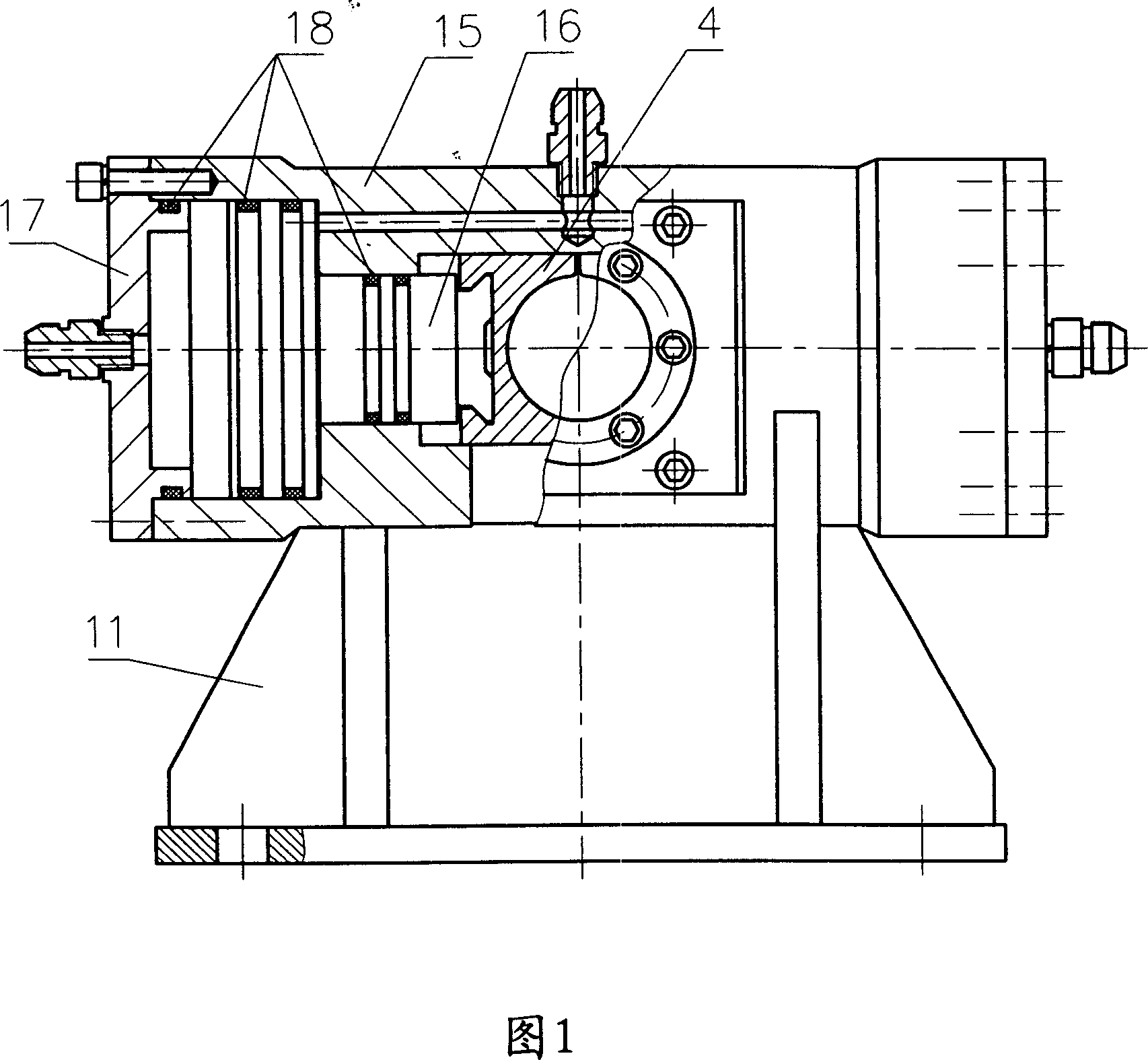
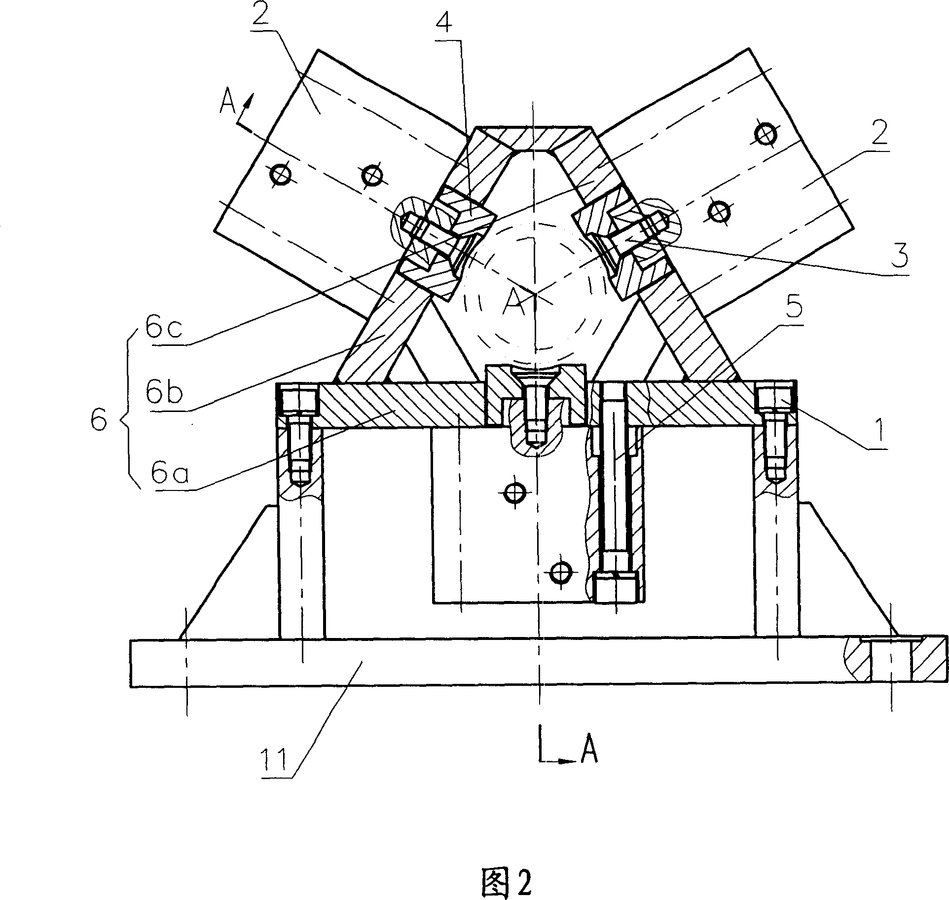
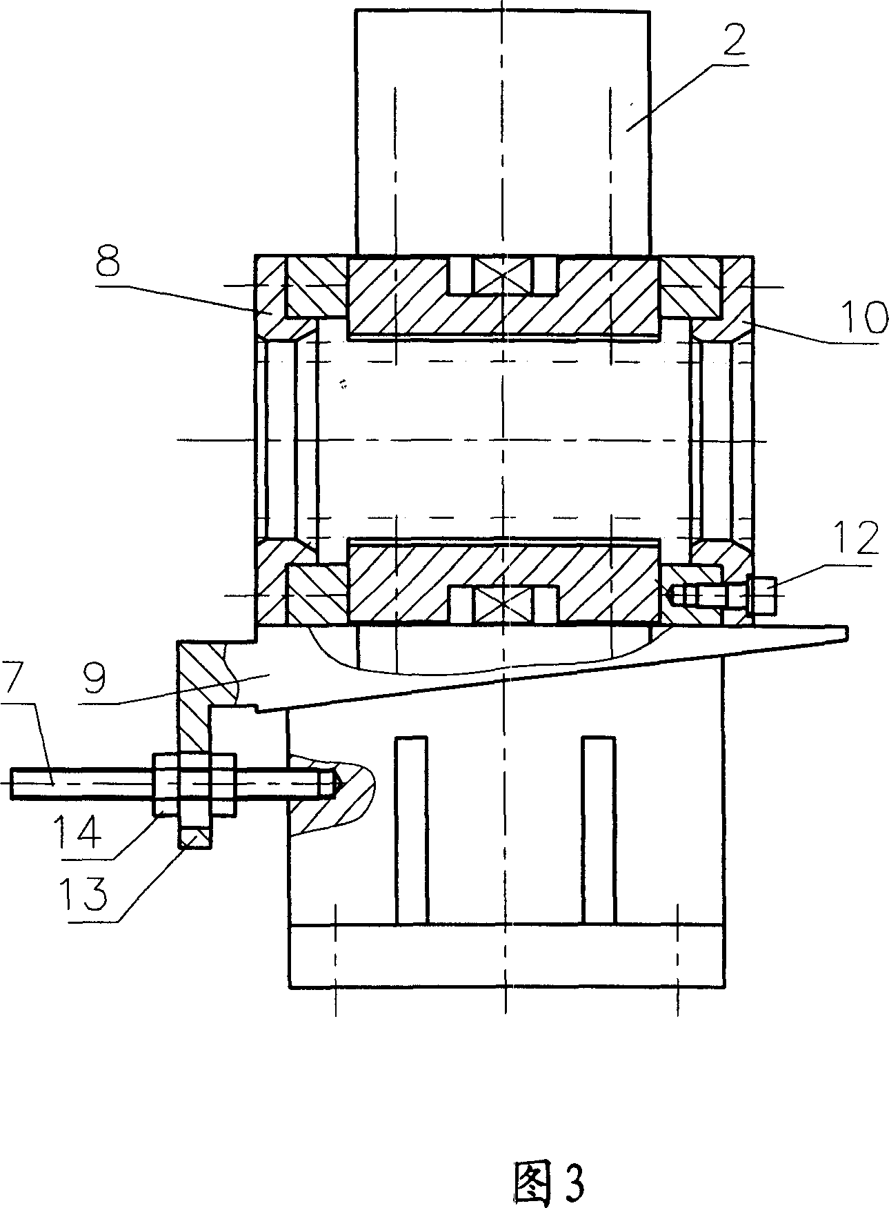
[0015] Such as figure 2 , image 3 As shown, the hydraulic clamper for the gas pumping and discharging drilling rig of the present invention is composed of a base 11, a support 6, slips 4 and a hydraulic cylinder 2. The support 6 has a bottom plate 6a and two side plates 6b, 6c, and the two side plates 6b and 6c are welded and fixed on the bottom plate 6a with the same inclination angle, the cross section of the bracket 6 is generally an equilateral triangle, the bottom plate 6a of the bracket 6 is installed on the base 11 through the bolt 1, the bottom plate 6a and the two side plates 6b, 6c are respectively A hydraulic cylinder 2 is installed with a bolt 5, and the piston rod of each hydraulic cylinder 2 is correspondingly connected with a slip 4, and the three slips 4 are evenly distributed around the circumference, and the geometric centers of the clamping parts of the three slips 4 coincide.

[0016] image 3 Show that between the base 11 and the support 6, a wedge blo...


PUM


Abstract

This invention relates to gas oil discharge hydraulic clamper, which comprises socket, rack, card tilt and hydraulic cylinder, wherein, the rack has one bottom board and two side boards with same angles fixed on bottom board; rack section area is of equilateral triangle; the rack bottom is fixed on socket through screw bolt; the bottom board and two side boards adopt screw bolt onto hydraulic cylinder with each piston bar connected with one card tilt.

Description

technical field [0001] The invention belongs to the technical field of drilling equipment for soil layers or rocks, and in particular relates to a hydraulic clamper for a gas pumping and discharging drilling rig. Background technique [0002] The gas drainage drilling rig is mainly used for drilling gas drainage holes, grouting fire extinguishing holes, coal seam water injection holes, outburst pressure relief holes, geological exploration holes or other engineering holes in coal mines. The hydraulic clamp is a key part of the drilling rig. Installation At the front end of the frame, it is used for guiding and clamping the drill pipe. Such as figure 1 As shown, the traditional hydraulic clamper for gas extraction and discharge drilling rig is mainly composed of a base 11, a housing 15, a piston 16 and a slip 4. The slip 4 is installed on the piston 16. A piston 16 and two slips 4, the clamping position of the slips 4 is in the shape of a semicircle, and its working princip...

Claims


Application Information

Patent Timeline
Patent Type & Authority Patents(China)
IPC IPC(8): E21B19/10E21F7/00
Inventor 李长江朱新才林顺洪
Owner CHONGQING UNIVERSITY OF SCIENCE AND TECHNOLOGY
Why Eureka
Try Eureka