Buffer structure for machine head of knitting machine

A cushioning structure and knitting machine technology, applied in the direction of mechanical equipment, shock absorbers, springs/shock absorbers, etc., can solve problems such as equipment damage, and achieve the effect of ensuring safe use, service life, and good cushioning effect

Inactive Publication Date: 2014-05-21
程林森
View PDF0 Cites 9 Cited by
  • Summary
  • Abstract
  • Description
  • Claims
  • Application Information

AI Technical Summary

Problems solved by technology

The traditional buffer mechanism directly uses the buffer head to be sleeved in the seat cover. After the knitting machine head runs out of control, it first hits the buffer head. When the buffer head is compressed by the impact force to the point that it cannot be compressed, the machine head will continue to hit the buffer seat forward. sleeve, resulting in a hard impact, resulting in damage to the knitting machine head and other equipment

Method used


Image

  • Buffer structure for machine head of knitting machine

Examples


Embodiment Construction

[0009] The specific implementation manner of the present invention will be further described below in conjunction with the accompanying drawings.

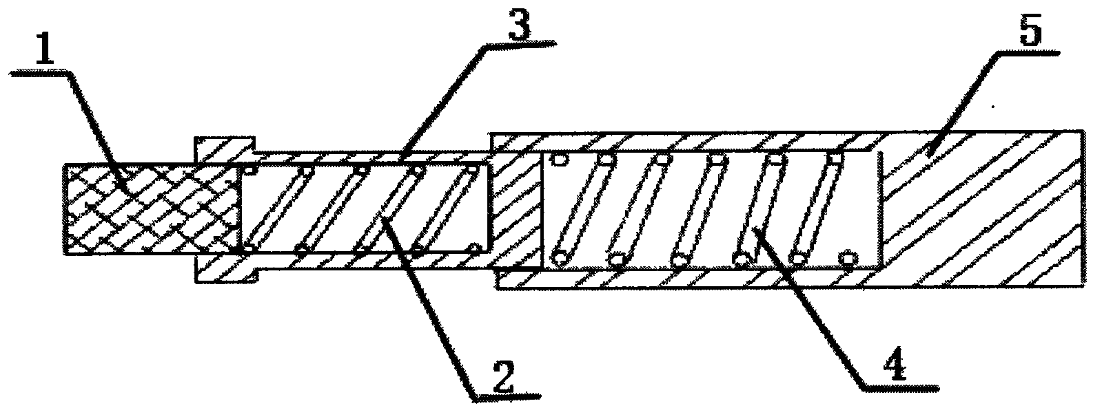
[0010] figure 1 As shown, a buffer structure of a knitting machine head includes a buffer head 1 , a first-stage buffer spring 2 , a first-stage buffer seat 3 , a second-stage buffer spring 4 and a second-stage buffer seat 5 . The outer end of the buffer head 1 is set correspondingly to the head of the knitting machine, the inner end of the buffer head 1 is slidingly arranged in one end of the first-stage buffer seat cover 3, and the inner end of the buffer head 1 is connected to the first-stage buffer seat cover through the first-stage buffer spring 2 3. The cavity at one end is driven by the first-stage buffer spring 2 to slide in the first-stage buffer seat cover 3; The other end of the seat cover 3 is connected to the second-stage buffer seat cover 5 through the second-stage buffer spring 4. The inner cavity at one end is driv...


PUM


Abstract

The invention discloses a buffer structure for a machine head of a knitting machine. The buffer structure for the machine head of the knitting machine comprises a buffer head and one or more levels of buffer base sleeves, wherein the outer end of the buffer head corresponds to the machine head, the other end of the buffer head is connected with a first-level buffer spring which is arranged in an inner cavity formed in one end of the first-level buffer base sleeve, the other end of the first-level buffer base sleeve is connected with a second-level buffer spring which is arranged in an inner cavity formed in one end of the second-level buffer base sleeve, the buffer base sleeves are connected in sequence, and the last buffer base sleeve is fixed to a machine tool body. The buffer structure for the machine head of the knitting machine is simple and compact in structure, the effect of multi-level sequential buffering is good, the machine head is effectively buffered, and use safety and the service life of the machine head are ensured.

Description

technical field [0001] The invention relates to a buffer structure of a knitting machine head. Background technique [0002] The function of the buffer structure of the knitting machine is to prevent the machine head from running out of control, to absorb the impact force of the machine head, to prevent the machine head from continuing to move out of control, and to prevent equipment damage. The traditional buffer mechanism directly uses the buffer head to be sleeved in the seat cover. After the knitting machine head runs out of control, it first hits the buffer head. When the buffer head is compressed by the impact force to the point that it cannot be compressed, the machine head will continue to hit the buffer seat forward. sleeve, resulting in a hard impact, resulting in damage to the knitting machine head and other equipment. Contents of the invention [0003] Aiming at the deficiencies of the prior art, the invention provides a knitting machine head buffer structure ...

Claims


Application Information

Patent Timeline
Patent Type & Authority Applications(China)
IPC IPC(8): F16F7/104F16F7/108
Inventor 程林森
Owner 程林森
Why Eureka
Try Eureka