Actuator, deformable mirror, adaptive optics system using the deformable mirror, and scanning laser ophthalmoscope using the adaptive optics system

A technology of adaptive optics and actuators, applied in optics, optical components, instruments, etc., can solve problems such as difficult movement

Inactive Publication Date: 2014-05-21
CANON KK
View PDF4 Cites 16 Cited by
  • Summary
  • Abstract
  • Description
  • Claims
  • Application Information

AI Technical Summary

Problems solved by technology

Therefore, in this structure, it is not easy to obtain a large amount of movement

Method used


Image

  • Actuator, deformable mirror, adaptive optics system using the deformable mirror, and scanning laser ophthalmoscope using the adaptive optics system
  • Actuator, deformable mirror, adaptive optics system using the deformable mirror, and scanning laser ophthalmoscope using the adaptive optics system
  • Actuator, deformable mirror, adaptive optics system using the deformable mirror, and scanning laser ophthalmoscope using the adaptive optics system

Examples


no. 1 example )

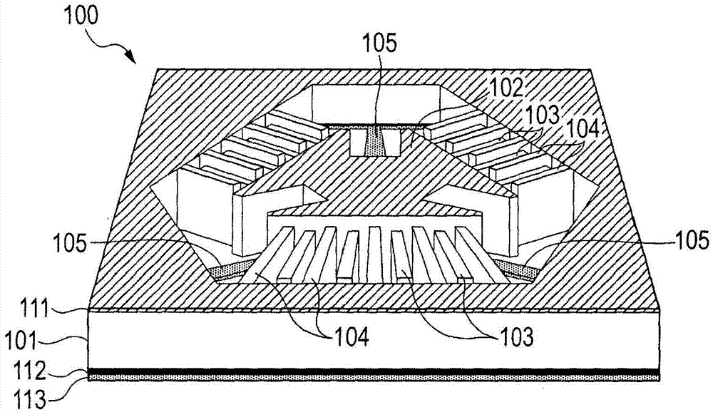
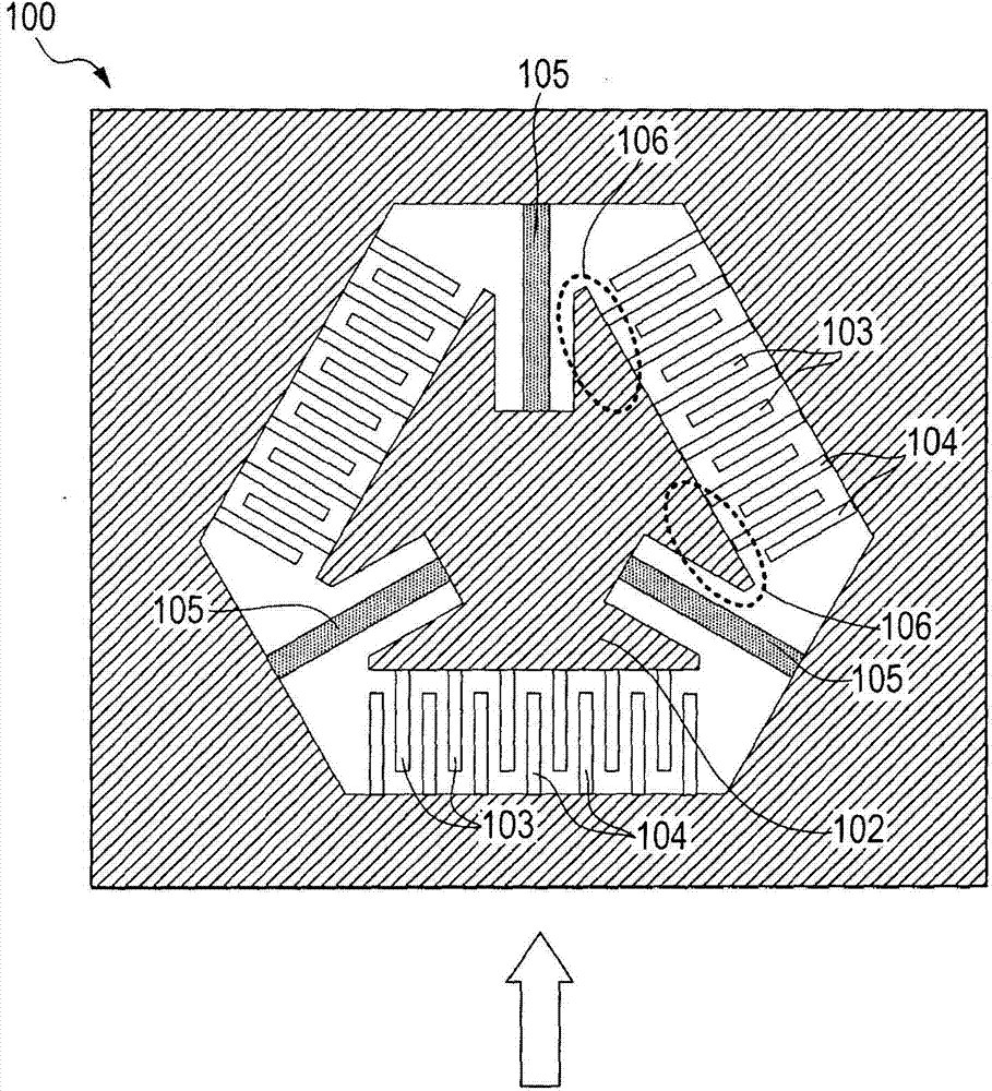
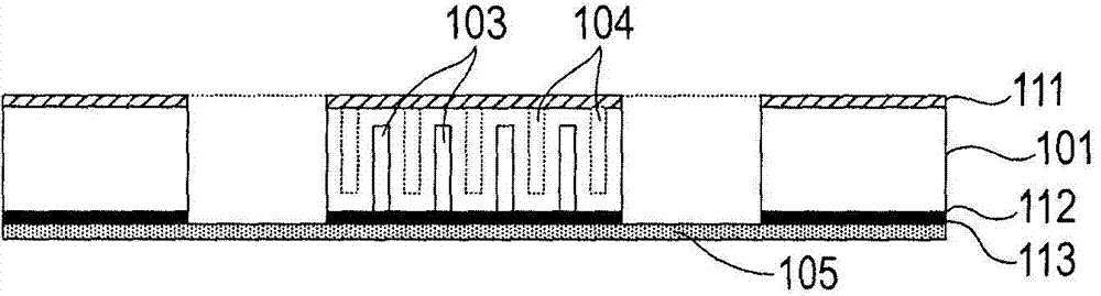
[0022] Below, refer to figure 1 and figure 2 , describing the actuator according to the invention. figure 1 is a perspective view of the actuator of this embodiment, and figure 2 is a top view of the actuator of this embodiment. The actuator 100 is formed by processing the plate-shaped substrate 101 . The movable part 102 is supported to the substrate 101 by at least three (in this case, three) elastic bodies 105 so as to be displaceable in a direction perpendicular to the surface of the substrate. Each elastic body 105 is formed of a leaf spring, a bar spring, or the like capable of being bent at least in a direction perpendicular to the surface of the substrate 101 . The movable comb electrode 103 includes a plurality of comb teeth each having one end supported by the movable portion 102 . Each comb tooth extends from one end supported by the movable part 102 in a direction parallel to the substrate surface. The fixed comb electrode 104 includes a plurality of comb...

no. 2 example )

[0034] A deformable mirror using the actuator of the first embodiment according to the second embodiment of the present invention is described.

[0035] Figure 4 and Figure 5 One mode of the deformable mirror according to the present embodiment is shown. Figure 4 is a perspective view showing a portion of a deformable mirror, and Figure 5 is a view showing the operation of the deformable mirror. In the deformable mirror, a plurality of actuators 100 according to the first embodiment are two-dimensionally arranged on a substrate 101 , and each of the actuators 100 is connected to a single mirror portion 120 via a connection portion 121 .

[0036] The structure and operating principle of each of the actuators 100 are the same as in Figure 3A and Figure 3B similar to that shown in . The deformable mirror of the present embodiment can obtain a desired shape by respectively displacing the movable parts 102 by respectively applying a potential difference between the comb...

no. 3 example )

[0040] An adaptive optics system using the deformable mirror described in the second embodiment as a wavefront correction device compensating for optical aberration is described with a scanning laser ophthalmoscope (hereinafter described as “SLO apparatus”) taken as an example. The SLO device is a device that irradiates the fundus with light to enable observation of a photoreceptor, a nerve fiber layer of the retina, hemodynamics, and the like.

[0041] Figure 9 A schematic configuration of the SLO device of this embodiment is shown.

[0042] Light emitted from a light source 201 travels through a single-mode fiber 202 and passes through a collimator 203 to become a collimated beam. The collimated beam is transmitted through a beam splitter 204 serving as a beam splitting device, and is guided to an adaptive optics system 220 as measurement light 205 . The wavelength of the light source 201 is not particularly limited, but particularly for fundus imaging, a wavelength of ab...


PUM


Abstract

The invention relates to an actuator, a deformable mirror, an adaptive optics system using the deformable mirror, and a scanning laser ophthalmoscope using the adaptive optics system. The actuator comprises a substrate, a movable portion provided so as to be movable with respect to the substrate, at least three elastic bodies for supporting the movable portion to the substrate in a displaceable manner, a movable comb electrode supported by the movable portion and extending in a direction parallel to a surface of the substrate, and a fixed comb electrode supported by the substrate and extending in the direction parallel to the surface of the substrate in which the movable comb electrode and the fixed comb electrode are arranged so as to be alternately engaged with each other with a distance, and each of all of the elastic bodies has a long axis that forms an angle of more than 90 DEG and 180 DEG or less with respect to at least one of the other elastic bodies.

Description

technical field [0001] The present invention relates to an actuator, a deformable mirror using the actuator, an adaptive optics system using the deformable mirror, and a scanning laser ophthalmoscope using the adaptive optics system. Background technique [0002] It is expected that a movable mirror of a type displaced by electrostatic attraction will be applied to various fields utilizing light. For example, a movable mirror can be used as an adaptive optical wavefront correction device to be installed in fundus examination equipment, astronomical telescopes, and the like. As a representative example of such a movable mirror displaced by electrostatic attraction, means enabling movement by using two parallel plate electrodes is known, but this parallel plate type has a disadvantage of a small amount of movement. [0003] In contrast to this, in recent years, deformable mirrors that use comb-like electrodes and can realize a large amount of movement have been proposed. An ...

Claims


Application Information

Patent Timeline
Patent Type & Authority Applications(China)
IPC IPC(8): G02B26/08G02B26/06A61B3/14A61B3/12
CPCG02B26/0841A61B3/1225A61B3/14H02N1/008
Inventor 岛田康弘尾崎裕之玉森研爾
Owner CANON KK
Why Eureka
Try Eureka